Showing posts with label drilling. Show all posts

Friday, March 22, 2019

The challenge to Drill the depth of the New Offshore Wells

drill the depth

About 80 kilometers from the coast, 1,500 meters below the water surface. The "numbers" of Macondo make an impression: just ten years ago the idea of ​​extracting oil on the high seas, at such high depths, was simply science fiction. And yet, faced with the greatest ecological disaster in the history of the oil industry, there is a comment that recurs with particular frequency among the experts: "BP was not dealing with a difficult well".

Over the course of a few years, the progress of offshore technologies has been so great that it has allowed companies to achieve the limits of the impossible, in front of which Macondo seems almost an amateur exercise. The Deepwater Horizon itself, the platform exploded on April 20, had just broken the submarine drilling record, identifying - again on behalf of BP and always in the Gulf of Mexico - the Tiber field, 10.6 km above sea level, of which over 9 under the backdrop.

There were 33 other offshore installations engaged in exploring the seabed at depths equal to or greater than those of Macondo in the United States. After the Macondo incident, the White House ordered that everyone stay for six months, waiting. of a crackdown on security conditions. The overall number of drills in the Gulf of Mexico, however, is much higher: according to the statistics of Rigzone, in April there were 243, of which about half were in use (in the world they were 578). As for the number of wells, the bottoms in front of Texas and Louisiana are literally studded with holes: it is estimated that there are about 3,500, dug with increasing frenzy as the search for crude oil on the mainland became more difficult, due to the decline of the most "at hand" fields and the spread of so-called resource nationalism. Technology has made it possible to make a virtue of necessity, with progress that in recent years has undergone a truly dizzying acceleration.

Oil was searched for the first time in water in 1938, at a depth of just 4 meters, with a few swimming strokes from Louisiana. The first really "offshore" well, 17 km off the same state, dates back to 1947: the platform was no bigger than a tennis court (the Deepwater Horizon had the size of a couple of football fields) and the crude was transported to land with barges taken by the Navy at the end of the Second World War.

It had to wait until the 1980s before Royal Dutch Shell managed to break the 1,000 foot deep (304.8 meter) threshold and up to 2000 to get to Macondo's 1.5 kilometer, with the Hoover Diana made by Saipem for ExxonMobil. Perdido - inaugurated last March 31 by Shell and capable of producing up to 100 thousand barrels of crude oil and 50 thousand cubic meters of gas per day - sinks its drills into the water for 3 km, more or less like five stacked Empire State Buildings.

But the real breakthrough in the offense is not only linked to the creation of increasingly powerful and sophisticated platforms, but to the new technologies for detecting the deposits, which allow to probe the depths, reconstructing images with three or even four dimensions of the potential deposits of hydrocarbons. This is how great discoveries have been made like that of Tupi, off the coast of Brazil, or Jubilee in the waters of Ghana. Discoveries that represent the future of oil. 
Read MoreThe challenge to Drill the depth of the New Offshore Wells

Thursday, March 14, 2019

Composition of Crude oil and Natural gas in Drilling


Relatively simple crude-oil assays are used to classify crude oils as paraffinic, naphthenic, aromatic or mixed, based on the predominant proportion of similar hydrocarbon molecules. Mixed-base crudes have varying amounts of each type of hydrocarbon. One assay method (US Bureau of Mines) is based on distillation, and another method (UOP "K" factor) is based on gravity and boiling points. More comprehensive crude assays are conducted to determine the value of the crude (i.e., its yield and quality of useful products) and processing parameters. Crude oils are usually grouped according to yield structure, with high-octane gasoline being one of the more desirable products. Refinery crude oil feedstocks usually consist of mixtures of two or more different crude oils.

Crude oils are also defined in terms of API (specific) gravity. For example, heavier crude oils have low API gravitates (and high specific gravities). A low-API gravity crude oil may have either a high or low flash point, depending on its lightest ends (more volatile constituents). Because of the importance of temperature and pressure in the refining process, crude oils are further classified as to viscosity, pour points and boiling ranges. Other physical and chemical characteristics, such as color and carbon residue content, are also considered. Crude oils with high carbon, low hydrogen and low API gravity are usually rich in aromatics; while those with low carbon, high hydrogen and high API gravity are usually rich in paraffin.

Crude oils which contain appreciable quantities of hydrogen sulfide or other reactive sulphur compounds are called “sour.” Those with less sulphur are called “sweet.” Some exceptions to this rule are West Texas crude (which are always considered “sour” regardless of their H2S content) and Arabian high-sulfur crudes (which are not considered “sour” because their sulfur compounds are not highly reactive).

Hidrocarbon:

Paraffins: The paraffinic saturated chain type hydrocarbon (aliphatic) molecules in crude oil have the formula CnH2n+2, and can be either straight chains (normal) or branched chains (isomers) of carbon atoms. The lighter, straight chain paraffin molecules are found in gases and paraffin waxes. The branched chain paraffins are usually found in heavier fractions of crude oil and have higher octane numbers than normal paraffins.

Aromatics: Aromatics are unsaturated ring type hydrocarbon (cyclic) compounds. Naphthalenes are fused double ring aromatic compounds. The most complex aromatics, polynuclears (three or more fused aromatic rings), are found in heavier fractions of crude oil.

Naphthenes: Naphthenes are saturated ring type hydrocarbon groupings, with the formula CnH2n, arranged in the form of closed rings (cyclic), found in all fractions of crude oil except the very lightest. Single ring naphthenes (mono-cycloparaffins) with 5 and 6 carbon atoms predominate, with two ring naphthenes (dicycloparaffins) found in the heavier ends of naphtha.

Non-hydrocarbons

Sulphur or sulfur and sulphur compounds: Sulphur is present in natural gas and crude oil as hydrogen sulphide (H2S), as compounds (thiols, mercaptans, sulphides, polysulphides, etc.) or as elemental sulphur. Each gas and crude oil has different amounts and types of sulphur compounds, but as a rule the proportion, stability and complexity of the compounds are greater in heavier crude oil fractions.

Sulphur compounds called mercaptans, which exhibit distinct odours detectable at very low concentrations, are found in gas, petroleum crude oils and distillates. The most common are methyl and ethyl mercaptans. Mercaptans are often added to commercial gas (LNG and LPG) to provide an odour for leak detection.

The potential for exposure to toxic levels of H2S exists when working in drilling, production, transportation and processing crude oil and natural gas. The combustion of petroleum hydrocarbons containing sulphur produces undesirables such as sulphuric acid and sulphur dioxide.

Oxygen compounds: Oxygen compounds, such as phenols, ketones and carboxylic acids, are found in crude oils in varying amounts.

Nitrogen compounds: Nitrogen is found in lighter fractions of crude oil as basic compounds, and more often in heavier fractions of crude oil as non-basic compounds which may also include trace metals.

Trace metals: Trace amounts, or small quantities of metals, including copper, nickel, iron, arsenic and vanadium, are often found in crude oils in small quantities.

Inorganic salts: Crude oils often contain inorganic salts, such as sodium chloride, magnesium chloride and calcium chloride, suspended in the crude or dissolved in entrained water (brine).

Carbon dioxide: Carbon dioxide may result from the decomposition of bicarbonates present in, or added to crude, or from steam used in the distillation process.

Naphthenic acids: Some crude oils contain naphthenic (organic) acids, which may become corrosive at temperatures above 232 °C when the acid value of the crude is above a certain level.

Normally occurring radioactive materials: Normally occurring radioactive materials (NORMs) are often present in crude oil, in the drilling deposits and in the drilling mud, and can present a hazard from low levels of radioactivity.
Read MoreComposition of Crude oil and Natural gas in Drilling

Saturday, March 9, 2019

WASHOUTS IN DRILLSTRINGS


Tool joint failure is one of the main causes of fishing jobs in the drilling industry. This failure is due entirely to the tool joint threads not holding or not being made properly. The make up torque puts the pin in tension and the box in compression, see Figure below. If the pin and box are not properly torqued, then the seals may separate under downhole conditions allowing the a leak path for the mud.

Each drillpipe joint has a pin and a box. Hence for a length of 1000 ft of drillstring there are 66 separate pins and boxes that need to mad up and broken regularly. The threads of the tooljoints seal at the shoulder area only. This feature requires that enough torque is applied during makeup to reduce the risk of having a loose connection in the drillstring. Leak paths within the tool joints develop if the seal is broken or if improper torque is applied. The leak path will lead to tool joint erosion by the drilling mud and if this erosion is severe enough that causes the surface of the pipe to be broken, the pipe is said to have a "washout".

Washouts can also develop due to cracks developing within the drillpipe due to severe drilling vibrations or cyclic loading, Figure below This is especially true in drillstrings rotating at RPM’s matching the drillstring natural (harmonic) frequencies. Washouts are usually detected by a decrease in the standpipe pressure, between 100 -300 psi over 5-15 minutes. This is easily distinguished from sudden drops in pump pressure which could be due to a lost jet nozzle or some surface leak. If a decrease in pump pressure is seen at surface, drilling should stop, pumping resumed. If the pump pressure is still less than before and a bit jet is not suspected to have been lost or no surface leaks detected, then the drillstring should be pulled out of a hole and the defective drillpipe joint should be replaced. Drilling records show that in some cases when a washout is suspected and the pipe was POH (pull out of hole), no cracks or washouts could be visibly seen on any of the drillpipe joints. The reason that the cracks could not been seen at surface is that under pumping and drilling conditions, the cracks open letting mud out and reduce the pump pressure requirements. When at surface, however, the drillpipe is under zero tension and the cracks therefore close escaping detection by the observer on the rig floor.

The author has come across several such situations when a washout is detected and when the drillstring POH, no defective pipe is seen. When the drillstring is re-run in hole, the pump pressure was still lower than before and in some cases it continued to drop. If drilling was resumed a twist off usually occurs resulting in a fishing job. To overcome this, it has been found useful in practice to pump a soft plastic line prior to POH. The soft line wedges itself into the crack(s) while the pipe is still down hole and whilst pumping, Figure below When the pipe is POH to surface, the defective drillpipe joint is easily noticed by the presence of the soft plastic line in the cracks.
Read MoreWASHOUTS IN DRILLSTRINGS

Wednesday, March 6, 2019

TYPES OF DRILLING CONTRACTS


business drilling deal contract


The type of Drilling Contract
  1.  TURNKEY DRILLING CONTRACT:

A type of financing arrangement (contract) for the drilling of a wellbore that places considerable
risk and potential reward on the drilling contractor. Under such an arrangement, the drilling
contractor assumes full responsibility for the well to some predetermined milestone such as the successful running of logs at the end of the well, the successful cementing of casing in the well
or even the completion of the well. Until this milestone is reached, the operator owes nothing to
the contractor. The contractor bears all risk of trouble in the well, and in extreme cases, may
have to abandon the well entirely and start over. In return for assuming such risk, the price of the
well is usually a little higher than the well would cost if relatively trouble free. Therefore, if the
contractor succeeds in drilling a trouble-free well, the fee added as contingency becomes profit.
Some operators, however, have been required by regulatory agencies to remedy problem wells,
such as blowouts, if the turnkey contractor does not.

 2. FOOTAGE DRILLING CONTRACT:

In the context of Oil & Gas law, a footage drilling contract refers to a contract in which the drilling contractor is paid to drill to a specified formation or depth. The drilling contractor is paid a set amount per foot drilled, and is given broad control over how to do the work. Under this kind of contract, the risk of unexpected delays along with other liabilities is on the contractor and not on the lease operator.

3. DAYWORK DRILLING CONTRACT

In relation to Oil & Gas law, a daywork drilling contract is one in which the lease operator hires a drilling rig and oilfield workers and retains the right to direct drilling operations. The lease operator pays an amount based on the time spent in drilling operations. This type of contract gives the lease operator broad control over the drilling contractor. As a result, courts impose broad liability on the lease operator for any damages caused due to the drilling.

4. COMBINATION DRILLING CONTRACT

The basis for payment is often combined in the final agreement. An Operator may agree to pay Footage rate to a certain depth, then pay daywork for any drilling done below that depth.
Read MoreTYPES OF DRILLING CONTRACTS

Tuesday, March 5, 2019

Extended Reach Drilling (ERW)

Drilling technology extended
Extended Reach Drilling

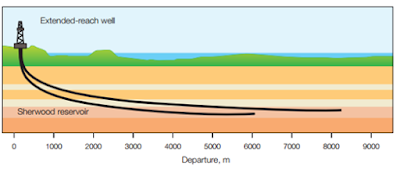
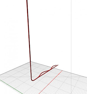
An extended-reach well is one in which the ratio of the measured depth (MD) vs. the true vertical depth (TVD) is at least 2:1.
Extended-reach wells are expensive and technically challenging, however, they can add value to drilling operations by making it possible to reduce costly subsea equipment and pipelines, by using satellite field development, by developing near-shore fields from onshore, and by reducing the environmental impact by developing fields from pads.
Extended Reach Drilling allows producers to reach deposits that are great distances away from the drilling rig and this help producers tap oil and natural gas deposits under surface areas where a vertical well cannot be drilled, such as under developed or environmentally sensitive areas.
Today, as the Horizontal Drilling, also the Extend Reach Drilling use the technology of the “RSS: Rotary Steerable System” that permit to steer an hole continuing the rotation of the drilling string with an improvement of the safety and the drilling efficiency.
Moreover, the selection of a drilling fluid must balance a number of critical factors.
The fluid must provide
  • a stable wellbore for drilling long open- hole intervals at high angles, maximize lubricity to reduce torque and drag, develop proper rheology for effective cuttings transport, minimize the potential for problems such as differential sticking and lost circulation, minimize formation damage of productive intervals.
Pipe rotation is another critical factor in hole cleaning.
The objective of the hole- cleaning program in ERW is to improve drilling performance by avoiding stuck pipe, avoiding tight hole on connections and trips, maximizing the footage drilled between wiper trips, eliminating backreaming trips prior to reaching the casing point and maximizing daily drilling progress.
Read MoreExtended Reach Drilling (ERW)

Friday, December 1, 2017

General Step and Procedure Oil Gas Drilling in Onshore


To find oil, you cannot simply punch a hole in the ground. Perhaps, this is what many people believe.
There are many complexities involving multiple service companies and two complete teams of crews. With so much happening (and with so many difficulties regarding scheduling, safety, and environmental practices) drilling for oil is not for the faint of heart.

This is a general 51 steps for drilling in the USA, for example. 

The following steps are necessary in order to produce oil or gas from a well:
  1. 10-30 different service companies are required.
  2. Each company working on a well must adhere to around-the-clock scheduling, safety and environmental practices.
  3. Build a new road to access the rig location.
  4. Clear the area for the new rig.
  5. Build infrastructure for water and electricity around the rig site.
  6. Dig an earthen pit to prevent soil or water table contamination.
  7. Dig a pilot hole at the precise location marked by the survey crew.
  8. Dig two other holes (the “mouse” hole and the “rat” hole) nearby to hold pieces of equipment and pipe during drilling.
  9. A rig that can dig a 10,000 ft. well requires 50-75 people and 35-45 semi-trucks to move and assemble the rig.
  10. Assembly of the rig takes around 3 and a half days.
  11. A strict inspection of the rig must take place once built.
  12. Operations of the rig go on 24/7, typically ceasing only one day each year for Christmas.
  13. Two shifts of two complete crews must work the rig every day.
  14. There are two stages of drilling: 1. running and cementing of cases and 2. drilling until the bit reaches the depth of the targeted zone.
  15. Each drill bit typically lasts 4,500 – 6,500 feet of drilling.
  16. Replacing the bit requires the removal of the entire string of drill pipe in a process called “tripping out”.
  17. “Tripping out” takes several hours and requires crews to cool the bit and keep the soil and hole intact.
  18. To help keep cuttings from plugging the hole, the mud must be sent through shakers to send the cuttings into a separated area.
  19. Additional mug system equipment: de-sanders, de-silters and de-gassers, remove smaller particles and gas from the mud.
  20. Clean mud is then recirculated back down into the hole.
  21. The Blow-Out Preventer (or “BOP”) is installed on top of the casing head before drilling takes place.
  22. The BOP must have high-pressure safetly valves designed to seal off the well and block any escaping gases or liquids from the hole beneath in order to prevent a blow-out from occuring.
  23. Drilling must begin with a designated surface depth, usually around 50-100 feet below the water table.
  24. Special care must be taken to prevent contamination of the water in the water table while drilling by isolating the water table and the wall with concrete and steel encasing.
  25. New sections of pipe must be added to the string as the bit drills deeper.
  26. When the hole reaches a designated depth, the derrickhands secrete fluid through the hole to condition it for logging.
  27. A “logging tool” measures the depth and condition of the hole for the oil company.
  28. The tool gives the information of whether or not the well can indeed produce oil or gas.
  29. At this point, it must be determined whether the well is to be complete or plugged and abandoned.
  30. If the well is designated as a producer, the crew must re-insert the pipe back into the hole to ensure the hole is still intact.
  31. To test the hole, mud must be re-circulated.
  32. Once everything tests positively, the drill pipe is removed.
  33. At this point, the crew must insert the last string of production casing running the entire depth of the hole.
  34. Then, the casing is cemented in the hole.
  35. The production crew then brings in the work-over unit and rigs it up to prepare the hole for production.
  36. The crew runs small diameter tubing into the hole as a conduit for oil or gas to flow through and up the well.
  37. Next, the work over unit trips out of the hole and picks up a perforating gun.
  38. The perforating gun is lowered into the hole to production depth using a thin metal cable called a “wireline”.
  39. An electrical signal is sent down the wireline, firing the gun and igniting explosive charges.
  40. These charges create holes through the cement encasing and formation connecting the well bore to the reservoir.
  41. To stimulate the flow of hydrocarbons (or oil), sometimes it’s necessary to “frack” the well.
  42. “Fracking” involves pumping air, sand and fluids under extreme pressure down the hole and out through the perforations.
  43. This fractures or forces cracks into the formation.
  44. The remaining particles will hold the cracks open, releasing the flow of oil or gas.
  45. Monitoring the flow allows the crew to determine the best location for the “choke”.
  46. The “choke” controls the flow of the oil or gas.
  47. Once pressure is released, the hydrocarbons are allowed the escape through the fractured zone and flow into the well bore.
  48. The oil or gas can now travel up the well casing string.
  49. The well bore is isolated from the surrounding formations with casing and cement, preventing any contamination.
  50. The final step is to install a pump jack or production well-head, or what’s called the “Christmas Tree”.
  51. It’s the time to produce the well and plan for any future field development.
Watch the Video : 


Read MoreGeneral Step and Procedure Oil Gas Drilling in Onshore

Thursday, November 30, 2017

Big Shale Technology

oil gas well drilling

Shale oil engineer Oscar Portillo spends his days drilling as many as five wells at once— without ever setting foot on a rig.
Part of a team working to cut the cost of drilling a new shale well by a third, Portillo works from a Royal Dutch Shell Plc office in suburban Houston, his eyes darting among 13 monitors flashing data on speed, temperature and other metrics as he helps control rigs more than 805 km (500 miles) away in the Permian Basin, the largest U.S. oil field.
For the last decade, smaller oil companies have led the way in shale technology, slashing costs by as much as half with breakthroughs such as horizontal drilling and hydraulic fracking that turned the United States into the world’s fastest-growing energy exporter.
Now, oil majors that were slow to seize on shale are seeking further efficiencies by adapting technologies for highly automated offshore operations to shale and pursuing advances in digitalization that have reshaped industries from auto manufacturing to retail.
If they are successful, the U.S. oil industry’s ability to bring more wells to production at lower cost could amp up future output and company profits. The firms could also frustrate the ongoing effort by OPEC to drain a global oil glut.
“We’re bringing science into the art of drilling wells,” Portillo said.
The technological push comes amid worries that U.S. shale gains are slowing as investors press for higher financial returns. Many investors want producers to restrain spending and focus on generating higher returns, not volume, prompting some to pull back on drilling.
Production at a majority of publicly traded shale producers rose just 1.3%over the first three quarters this year, according to Morgan Stanley. But many U.S. shale producers vowed during third-quarter earnings disclosures to deliver higher returns through technology, with many forecasting aggressive output hikes into 2018.
Chevron Corp. is using drones equipped with thermal imaging to detect leaks in oil tanks and pipelines across its shale fields, avoiding traditional ground inspections and lengthy shutdowns.
Ryan Lance, CEO of ConocoPhillips—the largest U.S. independent oil and gas producer—sees ample opportunity to boost both profits and output. ConocoPhillips also oversees remote drilling operations in a similar way to Shell.
“The people that don’t have shale in their portfolios don’t understand it, frankly,” Lance said in an interview. “They think it’s going to go away quickly because of the high decline rates, or that the resource is not nearly that substantial. They’re wrong on both counts.”
Shell, in an initiative called “iShale,” has marshaled technology from a dozen oilfield suppliers, including devices from subsea specialist TechnipFMC Plc that separate fracking sand from oil and well-control software from Emerson Electric Co., to bring more automation and data analysis to shale operations.
One idea borrowed from deepwater projects is using sensors to automatically adjust well flows and control separators that divvy natural gas, oil and water. Today, these subsea systems are expensive because they are built to operate at the extreme pressures and temperatures found miles under the ocean's surface.
Shell’s initiative aims to create cheaper versions for onshore production by incorporating low-cost sensors similar to those in Apple Inc.’s Watch, eliminating the need for workers to visit thousands of shale drilling rigs to read gauges and manually adjust valves. Shell envisions shale wells that predict when parts are near mechanical failure and schedule repairs automatically.
By next year, the producer wants to begin remote fracking of wells, putting workers in one place to oversee several projects. It also would add solar panels and more powerful batteries to well sites to reduce electricity and diesel costs.
Oil firms currently spend about $5.9 million to drill a new shale well, according to consultancy Rystad Energy. Shell expects to chop that cost to less than $4 million apiece by the end of the decade.
“There is still very little automation,” said Amir Gerges, head of Shell's Permian operations. “We haven’t scratched the surface.”
Technology, Geology
Much of the new technology is focused on where rather than how to drill.
“There is no amount of technology that can improve bad geology,” said Mark Papa, CEO of shale producer Centennial Resource Development Inc.
Anadarko Petroleum, Statoil and others are using DNA sequencing to pinpoint high potential areas, collecting DNA from microbes in oil to search for the same DNA in rock samples. ConocoPhillip’s MRI techniques also borrow from medical advances.
ConocoPhillips next year will start using magnetic resonance imaging (MRI) to analyze Permian rock samples and find the best drilling locations, a technique the company first developed for its Alaskan offshore operations.
EOG Resources Inc. last year began using a detailed analysis of the oil quality of its fields. The analysis, designed by Houston start-up Premier Oilfield Laboratories, helps to speed decisions on fracking locations and avoid less productive sites.
Premier has reduced the time needed to analyze seismic data to find oil reserves from days or weeks to seconds. Such efficiencies serve two purposes, said Nathan Ganser, Premier’s director of geochemical services.
“It’s not only removing costs thatare superfluous,” he said. “It’s boosting production.”
Read MoreBig Shale Technology

Tuesday, November 28, 2017

Geothermal Drilling with Kelly Rig


To make the hole or drilling well with kelly rig, energy must be transmitted from the surface to the rock face at the end of the wellbore. Power supply for drilling has evolved from the early days of steam-driven,mechanically coupled rigs to the current standard of diesel-electric drive. In this configuration, two to four diesel engines (up to 2,000 horsepower each) drive electric generators, which supply power to individual electric motors driving the rotary table, drawworks, mua pumps, and other equipment. The rotary table is a mechanism, usually inset into the rig floor, which turns the drill string to break rock and advance the hole. (A "drill string" comprises the drill pipe plus the bottom-hole-assembly, or BHA. The BHA includes drill collars, stabilizers, bit, and any other specialized tools below the drill pipe).

Hole diameters in oil and gas drilling usually range fiom 4 to 26 inches, while geothermal holes generally have a minimum production size of 8-112 inches. To drill these holes, torque is applied to the kelly, which is at the top of the drill string. The kelly is a section of pipe with a square or hexagonal outside cross-section which engages a matching bushing in the rotary table. This bushing lets the rotary table continuously turn the kelly and drill string while they slide downward as the hole advances.

The upper end of the kelly is attached to a 'hvivel", which is a rotating pressure fitting that allows the drilling fluid to flow fiom the mud pumps, up the standpipe, through the kelly hose, into the swivel, and finally down the drill pipe as it rotates. The swivel is carried by the hook on the traveling block and it suspends most of the weight of the drill string while drilling.

Moving the drill string or the casing into and out of the hole is called tripping. Trips are usually required because the bit or some other piece of downhole equipment must be replaced, or because of some activity such as logging, testing, or running casing, and of course trips take longer as the hole grows deeper. Raising or lowering the drill string for a trip is done by the drawworks, which is basically a large winch. (The swivel and kelly are almost always handled as a unit, and are set aside in the "rat hole" while tripping.) The drawworks reels in or pays out a wire rope (drilling line) which passes over the crown block at the top of the rig's mast and then down to the traveling block which carries the hook, which in turn suspends the drill string or casing. Depending on what mechanical advantage is required, the drilling line is reeved several times between the crown and traveling blocks, as in a block and tackle.


Read MoreGeothermal Drilling with Kelly Rig

Monday, November 27, 2017

Drilling with Coiled Tubing for Multilateral Wells

The petroleum industry is constantly driving to reduce capex and increase economic recoverability while minimizing environmental impact and surface footprint. By combining the three advanced drilling techniques of multilateral drilling, underbalanced drilling (UBD) and directional coiled tubing drilling (CTD), an operator can capture significant value out of known reserves.

The highest well productivity is achieved through maximizing reservoir contact per well/surface slot and minimizing reservoir damage. Multilateral drilling reduces capex through drilling multiple reservoir sections per surface slot while also increasing reservoir contact per surface slot. UBD minimizes reservoir damage, which maximizes the productivity of each lateral. CTD is inherently set up for underbalanced operations (UBCTD), and CTD bottomhole assemblies (BHAs) can achieve high build rates of up to 50 degrees per 30 m (100 ft) to allow multiple targets to be accessed from the mother wellbore.

Selecting a BHA

A directional CTD BHA consists of a coil connector, cablehead, electric or mechanical disconnect, downhole orienter, sensor package, motor or turbine with a bent housing, and a drillbit. Drilling directionally on coiled tubing (CT) is similar to conventional slide-and-rotate drilling on a rotary. As CT cannot be rotated from surface, all the rotation needs to be carried out downhole through the orienter. The rotating orienter allows the toolface to be set from surface or for the motor to be rotated to drill a straight hole.

Service companies also can provide additional BHA modules such as a gyro module for orienting a whipstock and for drilling in the presence of magnetic interference immediately after exiting the casing.

CT drilling faces two fundamental challenges: transferring weight to the bit and length limitations of the lateral sections. If the well trajectory plans for high doglegs, then it can be difficult to transfer weight to the bit. This is accentuated by the inability to rotate the whole drillstring as in conventional drilling. It is essential to have a weight-on-bit (WOB) sensor in the BHA so the driller can see that the weight is actually being transferred to the bit and react accordingly. The length of laterals that can be drilled with CT also are affected by the tortuosity, but this is particularly true in horizontal sections. The more tortuous the wellbore, the shorter the lateral length will be. CTD BHAs that have a continuous rotating orienter prevent this tortuosity from occurring and therefore maximize the available WOB and lateral length (Figure 1).


FIGURE 1. A straight wellbore increases the potential length of a lateral section compared to a wavy wellbore. (Source: AnTech)


Designing a multilateral well

All well designs require a multidisciplinary team to be successful. When designing a multilateral well, an integrated team of subsurface specialists and directional drilling specialists is even more essential to successfully drill the well. The well design and completion strategy is heavily affected by the reservoir characteristics, horizontal and vertical permeability, the geological structure, and geosteering requirements. The first step is to clarify if significant productivity gains can be made from utilizing multilaterals over other techniques. Once established, it is an iterative process between the directional drilling contractor and the operator’s engineering and subsurface teams to find the best way to design the well.

There are a near-infinite number of wellbore paths for multilateral wells. The two most common are stacked laterals and forked laterals (Figure 2). Stacked laterals can access different layers of a laminated reservoir. Forked laterals are all at a similar depth and are most commonly used to increase reservoir contact in a specific formation. Clarifying the objective for the multilaterals early on helps reduce the number of iterations required of the trajectory.


FIGURE 2. Stacked laterals offer access to different layers of a laminated reservoir, while forked laterals are at a similar depth and help increase reservoir contact in a specific formation. (Source: AnTech)


Once the trajectories are drafted, the wells must be modeled to ensure drillability and to specify surface equipment. For the CTD section the main areas for analysis are the available WOB, CT lock-up limit, borehole cleaning and surface pressures. The CT can be specified from these models. Production and geomechanics models also must be run to ensure the separation equipment is suitably specified and the amount of the underbalance applied to the wellbore does not cause wellbore stability issues.

Sidetracking techniques

To create the additional well path from the mother wellbore, a sidetrack must be initiated. There are two main categories of sidetracking a well: cased-hole sidetracks and openhole sidetracks. The cheapest and fastest way to carry out a cased-hole sidetrack is to use a whipstock and a window milled in the casing rather than section milling.

Multiple whipstocks can be set in the mother wellbore and retrieved if required. For openhole sidetracks the drilling BHA is used to create a trough in an inclined section of the wellbore. Once the trough is initiated, the WOB can be increased to carry on the borehole section. An openhole sidetrack also can be initiated off a cement plug with special procedures.

Since CTD BHAs operate on wireline, this allows significant amounts of real-time data to be received from the BHA. This helps to speed up the sidetracking process because rather than relying completely on time drilling, the directional driller can see the WOB and torque-on-bit responses to each operation and optimize on the fly. This is the case with both openhole and cased-hole sidetracks. A special module is required to monitor the casing milling operations since the vibration levels are so high.

Geosteering

A multilateral will not provide a good return on investment if the laterals are not drilled into the target zones. The options for geosteering on UBCTD are relatively limited compared to a conventional LWD service. Gamma ray and resistivity are available on certain CTD BHAs. A biostratigraphy service also can be used to identify changing formations. The UBD package can provide a significant amount of data that can be used for geosteering and reservoir characterization while drilling. The large amount of additional information that can be gathered from the real-time downhole sensors and the UBD package, if used correctly as part of an integrated data acquisition and reservoir evaluation strategy, can remove the need for expensive LWD tools or wireline logs.

Drilling practices

Drilling on CT has been avoided in the past due to concerns over stuck pipe and borehole cleaning issues. When drilling reentry wells using CTD, the borehole size is usually closer to the BHA size than in conventional drilling. In addition, since the pipe is not rotated, a greater focus needs to be placed on good borehole cleaning practices. Every CTD project must be modeled and analyzed to ensure the well can be drilled successfully. When drilling the borehole sections, the real-time drilling parameters must be monitored to identify any indications of borehole problems. Drilling practices also are adapted to ensure the borehole is clean and free of ledges. For example, a short trip must be made at every 46 m (150 ft) to ream the borehole, and at every 91 m to 137 m (300 ft to 450 ft) a long trip back to the casing window must be made. Because the driller is able to see these changes in downhole conditions at surface, there is an opportunity to prevent these issues and optimize the uptime of the operation.
Read MoreDrilling with Coiled Tubing for Multilateral Wells

Rig Automation Maximizes Value For Contractors And Operators

oi gas drilling equipment

Drilling a well is a complex mix of overwhelming data and tasks in need of constant attention. To address the challenge of repetitive complexities of machine and process control, the NOVOS process automation platform was launched by NOV after an extensive development period.

The system provides a common platform for the control, monitoring, scheduling and optimization of drilling operations. This enables drillers to focus on what is important while they consistently execute repetitive drilling activities to achieve the well program by integrating the best of human and equipment capabilities.

offshore rig

The NOVOS process automation platform manages rig equipment to execute drilling programs, allowing the driller to focus on safety and process execution. (Source: NOV)


Compatibility

The structuring of data and defining activities through process automation enables engineers to develop lessons learned and apply best practices across regions and rig fleets, regardless of rig specifications or location. The system is scalable, not custom-built, so it does not require extensive R&D for it to work with each new deployment.

NOVOS is simply dropped on top of the existing NOV control system, creating a quick and rapid deployment. The scalable installation enables the system to be easily placed on rig fleets, which increases overall consistency, enhances the performance of the entire fleet and gives the end user the ability to plan ahead.

The system is equipped with applications that immediately allow the rig to drill faster, safer and more effectively. It also has the capability to incorporate customized applications for specific drilling requirements.

A software development kit allows developers to create and deploy their own optimization applications that use sensor data to control rig machines. Third parties are provided with safe access to a wide variety of functions within the system and encouraged to develop applications that address their unique challenges. Those applications can then be layered, prioritized and partitioned to provide simple flexibility of control and monitoring in ways that were previously unachievable.

There are five major operators and service companies working to develop applications compatible with the platform, with development pending with nine more companies.

The platform today

Years of development were spent to ensure NOVOS was built with a foundation of stability, flexibility and ease of scalability to be valuable in bringing practical automation to the drilling process.

In the years since its launch the platform has successfully been installed and commissioned on 19 land rigs. There are five additional installs scheduled but pending rig availability. The system is installed on rigs in Oklahoma, Pennsylvania, Texas and Canada. Precision Drilling currently has the system installed on 18 land rigs. In second-quarter 2017 a system was purchased by Beaver Drilling for installation on its Rig 15.

The NOVOS team is actively training drillers on rig location depending on rig and resource availability. During the training process drillers are easily picking up the system and becoming even more proficient over time.

Value in the numbers

NOVOS was recently deployed during a rig move for Precision Drilling. The early results showed the company’s drillers achieved consistent bottom-to-bottom time savings—a 10% improvement bottom-to-slips, 18% faster add-stand and a 67% improvement slips-to-bottom—yielding overall time savings of 41% per connection.

To evaluate connection time improvements, NOV compared the five best consecutive bottom-to-bottom cycles for conventional drilling against five consecutive cycles of NOVOS-enabled drilling. There was a reduction in average bottom-to-bottom time from 7.91 minutes to 4.67 minutes using NOVOS, demonstrating a significant improvement in Precision’s performance. The increased consistency created by automating repetitive tasks resulted in an increased awareness of safety and successful delivery of the overall drilling operation.

Assuming six wells per pad and 20 total days of drilling time per well, connection time savings translated to nine hours saved per well and 2.25 days saved per pad on average, enabling the drilling contractor to better plan service delivery, allocate resources and move quickly to the next pad. The total savings added up over time yielded higher profits and rates of return on the customer’s initial investment.

drilling operation

Precision Drilling saw a savings in overall connection-to-connection time and delivered a consistent drilling process with its use of NOVOS. (Source: NOV)


Next steps

As NOVOS begins to make its way on to several rigs, the surface is just being scratched on how the automation can be used. There are many repetitive functions that are still performed manually that can be brought into the control system. Right now, consistent and repetitive tasks are automated on the drill floor, but there are other areas on the rig where repetitive tasks could be automated.

Features added since the release of NOVOS include, but are not limited to, reaming, rocking, torque and drag, and a downlinking interface. The ease of updates and enhancements further shows the flexibility of the NOVOS platform. As for next steps, an improved user interface based on driller feedback also is being developed. The additional features and new user interface are scheduled to be released in third-quarter 2017, and work toward finalizing offshore capabilities for gel breaking and envelope protection are underway.
Read MoreRig Automation Maximizes Value For Contractors And Operators

Sunday, November 26, 2017

Digitalization Directional Drilling


Super-specification pad-optimal Swiss Army-style walking rigs may generate headlines when it comes to evolution in land drilling, but directional drilling is fast becoming a more accurate indicator of how the sector is evolving as tight formation development enters full field development.

Companies like Baker Hughes, a GE company, have offered sophisticated geo-steering suites combining bits, motors, downhole evaluation and software control to improve ROP for some time. But quietly, and without fanfare, the largest domestic land drilling contractors and their Canadian peers are integrating digital directional drilling capabilities into rig offerings.

The trend accelerated over the last six months when land contractors began purchasing digital directional drilling providers. Acquisitions include Helmerich & Payne IDC’s $100 million purchase of Motive Drilling Technologies Inc. in May, Patterson-UTI Energy Inc.’s $215 million cash and stock purchase of MS Energy Services and Trinidad Drilling Ltd.’s $40 million cash and stock acquisition in August of RigMinder Inc. and its electronic data recorder and bit guidance systems, which integrate the rig and directional drilling tools.

Other drillers, including Nabors Industries Ltd. and Ensign Energy Services Inc., offer directional drilling services and supporting downhole packages that include proprietary mud motors and MWD tools integrated with software to improve directional drilling performance. Nabors, for example, is commercializing a multiple package software suite that includes its recently developed ROCKit directional steering control system.

Meanwhile, Canada’s Precision Drilling aims to “de-man” the directional drilling process via a proprietary directional guidance system that coordinates workflow between the rig’s driller on location and a remote directional driller who oversees several directional drilling projects simultaneously. Precision is using algorithms to convert 14 process and 20 decision points in directional drilling into seven processes and 10 decisions, reducing support crew, time and cost. The system will be fully deployed across Precision’s fleet in 2018.

What’s going on? At the simplest level, it is an opportunity for drilling contractors to capture more revenue per rig in a flat pricing environment. Beyond that, larger drillers are bringing in-house a service that is integral to today’s best practices where precise lateral landing in extended wellbores is as important for boosting hydrocarbon recovery as greater proppant loading.

Digitally enhanced directional drilling integrates software suites, sensors and downhole tools to reduce wellbore tortuosity and generate higher ROP. Digital directional drillers  point to field-tested savings in time and direct costs that are measured in tens of thousands of dollars per well.

Digitalization of directional drilling is disruptive technology. The question is whether it will supplant both personnel and the community of independent service providers.

One other factor promoting the spread of digital directional drilling is that the software is often independent of the rig, allowing smaller contractors to integrate the service into their own rig offerings via third-party access.

Like all wellsite technology, digital directional drilling may require an evolutionary step in perception at the well site that also incorporates specialized human input and flexibility as the best solution for sophisticated problem-solving in a dynamic environment.

Source:Shutterstock.com
Read MoreDigitalization Directional Drilling

Solids Control Innovations To North American Shale Fields


While the last year has seen a ramping up of onshore drilling in shale fields across North America, it’s clear that “caution” still remains the watchword when it comes to drilling and production budgets.

Anadarko, ConocoPhillips and Hess already have announced reductions in 2017 E&P budgets, and in the words of Anadarko CEO R.A. Walker, “We sincerely believe the volatility of the current operating market requires financial discipline.”

Such volatility and the focus from shale operators and drilling contractors on financial discipline, reduced costs and increased efficiencies is shining the spotlight on a key sector of the drilling market—solids control.

Drilling fluids play a crucial role in drilling activity in shale fields, cooling and lubricating drillbits, carrying drill cuttings to the surface, controlling pressure at the bottom of the well and ensuring that the formation retains the properties defined for that well.

The effectiveness of such fluids is highly dependent on solids control and the ability to separate the mud from rock particles and low-gravity solids so that clean mud is recycled and circulated back into the drilling system. If there are too many solids in the mud, ROP is reduced, and torque, drag and abrasion are increased as well as potential lost circulation and production.

The more capable the drilling rigs and the better the solids control technologies, the greater the drilling efficiencies and levels of potential production.

Current technology limitations

Shale shakers separate drill cuttings by passing the muds through a shale screen with separation achieved by vibrations and high G-forces. But there are limitations to these devices.

First, there is the capex and opex required for the shale shakers—not a one-off cost but a drag on finances throughout operations due to the need for the shale screens to be continually replaced.

There also is more onsite equipment, personnel, and greater costs and HSE risk.

Also, there are the inefficiencies of the shale shaker-based process itself.

The drilled solids are often broken down into fine particles that are difficult to remove, leading to an increase in solids in the drilling fluid, a decline in drilling fluid efficiency and a negative impact on penetration rates and equivalent circulating density.

Another downside of vibrating-type shale shakers is higher volumes of mud being lost and more drilling waste generated. One industry guru working for a major operator once said that 15% of all the mud used per well is lost in some form or another via the shakers.


Viable alternative
It’s with these issues in mind that Cubility’s filter beltbased MudCube technology is proving an effective alternative to shale shakers in shale fields.

The MudCube is an enclosed vacuum-based system that eliminates the traditional process of shaking fl uid and solids. Instead, drilling fl uids are vacuumed through a rotating filter belt that uses high airfl ow to separate the cuttings from the fl uid.

The cleaned drilling fl uids are then returned to the active mud system, and the drilled solids are carried forward on the filter belt for disposal. As opposed to shakers, the MudCube processes 100% of the mud, immediately increasing performance.

The system also eliminates the need for multiple shaker panels, with the solids removal efficiency also ensuring that as much as 80% more mud is recovered than competing technologies, which is a huge benefit when multiplied by several onshore rigs.

The improved separation capabilities of the MudCube also lead to better quality drilling fluid, more drilling fluid recycled back to the mud tanks to be reused for drilling, less waste and improved drilling efficiencies with stable drilling fl uid properties and a decrease in nonproductive time.

There are also the financial benefits of avoiding screen replacements on a regular basis—filter belts need replacing but not at such fast rates.

In addition, the MudCube is a much more compact alternative to shale shakers. A typical three-deck shaker weighs about 3 metric tons compared to 1 ton for the MudCube.

Deployments across North America

The MudCube’s easy installation on drilling pads is ensuring that it can impact the bottom line almost immediately.

In 2016 Cubility partnered with EQT Corp., and the MudCubes were successfully deployed to an onshore fl uid rig that was drilling Marcellus wells in western Pennsylvania. Cuttings were easily lifted out of the wellbore, leading to immediately improved solids control and waste disposal.

The MudCube also has been successfully deployed for Murphy Oil in Canada, and the company is evaluating the service for possible use in the Eagle Ford Shale as well.


New Tech Solids Inc. and the MudCube delivered dry cuttings with Murphy Oil in Canada. (Source: Cubility)


Mending the broken value chain

Cubility also is looking to contractor partnerships and offering the MudCube as a rentable system to enable contractors to embrace the latest solids control innovations and address the broken value chain where operators drive down day rates, leaving contractors with little scope for new equipment.

To this end Cubility is partnering with Houston-based Stage 3 Separation in providing a modular, easy and inexpensive installation and operation of MudCube, a system specifically designed for onshore shale operations and that can be up and running in a matter of days as an integrated part of the rig design.

It’s through exclusive distribution partnerships such as this and also with Canadian-based New Tech Solids Inc. (a recent deployment is taking place with Shell via New Tech Solids) that the next few years is likely to see more and more MudCubes deployed across North American shale fields through these service providers.

In today’s tight but ultrafast land drilling market, any solids control solution must provide immediate “wins” in terms of reduced costs and increased efficiencies. Vacuum and filter belt-based enclosed solid control systems are achieving this. 
Read MoreSolids Control Innovations To North American Shale Fields

Extend Lateral Reach with Buoyancy-assisted Casing Equipment (BACE)


A major challenge in lengthy horizontal or highly deviated wellbores is running the casing string to depth. Drag between the casing string and the formation can often exceed the load capacity of the casing hook, preventing tools from reaching optimal setting depth. This challenge is compounded in shallow horizontal wells. Finding a way to minimize the drag is the key to extending the reach of highly deviated and horizontal wellbores.

A technique developed to “float” the casing into the wellbore using buoyancy-assisted casing equipment (BACE) allows operators to run casing to the bottom of these particularly challenging wellbores. Paired with floating equipment, the application of BACE traps lightweight fluid or air in the lower section of the casing string, thereby reducing the weight of the casing. The lighter weight reduces drag by lifting the casing string away from the formation wall and minimizes the surface area contact of friction.

This technique enables increased running depth and decreased potential for casing buckling or sticking. To simplify its application, BACE is fully integrated with the casing string, and it helps reduce risk because it has no outer shear pins posing potential leak points. Additionally, the tool doesn’t require debris barriers that can obstruct free flow in the casing. As opposed to other methods or alternatives, BACE does not leave behind any trace of rupture disc within the casing wall, which can impair fracture plug deployment during plug-and-perf operations.

Three recent jobs in unconventional shale plays involving lengthy lateral casing strings illustrate the effectiveness of the BACE technology to overcome challenges.

Reaching out in the Western Hemisphere

In the first case study an operator planned an extended lateral well of about 3,962 m (13,000 ft), anticipating challenges getting the casing to planned depth. The operator also was concerned about the compatibility of equipment throughout the casing string for cementing and future operations.

Halliburton performed analysis on the wellbore and determined that the best way to set the casing would be to use BACE along with a fullbore pressure-operated fracturing sleeve. Additional torque and drag analysis identified the need to create a buoyant chamber at the heel of the wellbore.

While the service company was executing the job, BACE ruptured at the planned applied casing pressure. After successfully removing the buoyant air chamber, technicians launched the bottom plug from the surface, landed it down on the BACE plug and released it to initiate displacement. During the cement job the plugs were successfully pumped through the RapidStart Initiator Casing Test without incident, proving compatibility and allaying concerns the operator had in the planning stage.

Challenges in the Eastern Hemisphere

In the second case study an operator planned to run about 3,200 m (10,500 ft) of casing in a lateral wellbore and achieve both planned total depth (TD) and topof- cement for zonal isolation. Because the job would be the operator’s longest lateral, it was extremely concerned about successfully executing to plan.

Halliburton performed torque and drag analysis using the wellbore parameters and determined BACE would be the best course of action placed at the heel of the wellbore. Additionally, cement design modeling suggested the use of an external sleeve inflatable packer collar (ESIPC) for second-stage cementing. Executing the job, the extended- reach casing was floated to planned TD using BACE, and the success of the run eliminated the contingency of running a smaller liner to achieve TD. All displacement measurements for the cement plugs and the BACE were in accord with the job design, and the ESIPC functioned properly, enabling the displacement of the second-stage cementing to achieve planned top of cement.

Specialty casing application with fiber optics

In the third case study an operator sought to set casing in a well with a true vertical depth of 3,246 m (10,650 ft), a measured depth of 6,390 m (20,967 ft) and a bottomhole temperature of 137.7 C (280 F). The operator also wanted to run fiber optics as it considered the well something of a “science project” to monitor in situ conditions and provide data for future well development in the area.

The Halliburton team proposed using BACE and, after conducting torque and drag analysis with wellbore conditions, it determined the technology would work best near the heel of the wellbore. The subsequent four months of planning and preparation for the job entailed mobilizing the necessary downhole tools, surface equipment and field personnel to the site and conducting a critical well review to ensure all elements of the operation were coordinated.

The execution phase began with the team positioning the BACE about 2,438 m (8,000 ft) from the end of the string and then successfully floating the casing and fiber optics to TD. Next, pressure inside the casing was increased to 1,250 psi and ruptured the disc as planned, which separated the 10 parts per gallon well fluid from the air-filled chamber. Finally, the team circulated about 1,000 bbl of fluid to ensure that all of the air in the buoyancy chamber was depleted, after which the cement job was performed.

With critical data being fed back to the operator, the BACE provided a successful outcome, according to the operator. During the planning phase the operator estimated the job of running fiber optics with the casing would take three to five days at a pace of running about four joints of casing per hour. By using BACE the operator was able to run about 14 joints of casing per hour and cut three days from the operation, reducing time and costs.

As lengthy horizontal and highly deviated wellbores become increasingly common, the application of this type of technology could become a more widely used technique in more places around the world.

source: www.epmag.com
Read MoreExtend Lateral Reach with Buoyancy-assisted Casing Equipment (BACE)

Oil Exploration With Gravity And Magnetic Geophysical Methods

Gravity and magnetic methods are an essential part of oil exploration. They do not replace seismic. Rather, they add to it. Despite being comparatively low-resolution, they have some very big advantages.

These geophysical methods passively measure natural variations in the earth’s gravity and magnetic fields over a map area and then try to relate these variations to geologic features in the subsurface. Lacking a controlled source, such surveys are usually environmentally unobjectionable.

At a comparatively low cost, airborne potential field surveys can provide coverage of large areas. Allowing quick regional coverage, even gravity surveys can now be recorded from an aircraft with airly high reliability.

In Canada, digital regional gravity and magnetic data are available at zero cost from federal government agencies. Local and detailed surveys are acquired by exploration companies.

Because many college programs tend to overemphasize seismic as almost the only geophysical tool for oil exploration, other methods are sometimes overlooked by explorationists and managers. Where useful gravity and magnetic data are disregarded, risk reduction is incomplete, and the results of exploration programs are less reliable.

What anomalies mean

The physical rock property that links gravity anomalies to rock composition is density. The rock property that links magnetic anomalies to rock composition is total magnetization. Thus, each potential-field method valuable provides its own picture of the subsurface.

Density is scalar, but magnetization is a vector total of a vast and commonly unpredictable variety of remanent and induced magnetizations. Unlike density, magnetization can depend on very slight variations in the occurrence and distribution of particular minerals, which may have little relation to the overall lithology.

A geophysical anomaly is the difference between the observed (measured) geophysical field value and the value that would be observed at the same location if the Earth were more uniform. Nonuniformities in the physical properties of rocks give rise to geophysical anomalies.

Being responsive to lateral variations in rock properties, gravity and magnetic methods are best suited for detecting steep discontinuities such as faults. Seismic methods, by contrast, are best for detecting vertical rock variations and low-angle discontinuities such as layer boundaries.

The gravity field is simple, unipolar and almost perfectly vertical. The geomagnetic field is complicated: It has two or more poles, and it is commonly strongly nonvertical. Besides, it changes all the time, necessitating frequent updates by government agencies.

Gravity lows (negative anomalies) occur where rocks in the subsurface have a comparatively low density, which reduces their downward gravitational pull. Where the rock density is relatively high, the gravitational pull is increased, and a gravity high (positive anomaly) occurs.

Magnetic anomalies are more complex because the magnetic field and rock magnetization are both complicated. With a nonvertical dipolar field, a single rock-made anomaly source can be deceptively associated with a pair of apparent anomalies: a high and a low side by side.

Gravity and magnetic surveys should be designed purposefully to resolve the specific kind of anomalies that are expected from geologic targets of interest in a particular study.

Gravity and magnetic surveys should be designed purposefully to resolve the specific kind of anomalies that are expected from geologic targets of interest in a particular study. If a survey is too tight, money is wasted on redundant coverage. If a survey is too sparse, the desirable anomalies are undersampled and not delineated sufficiently. The idea is to design the sparsest and smallest, hence cheapest, survey that would resolve all the expected desirable anomalies.

Examples of exploration use

In the platformal Phanerozoic Alberta and Williston basins, most big magnetic and gravity anomalies are associated with ductile structures and rock composition variations in the crystalline basement inherited from orogenic events in the Precambrian. Such ductile ancient structures were fairly seldom reactivated, and they had relatively little influence on the Phanerozoic basins above.

More important are the later brittle basement faults and fractures, whose offset can be as little as a few meters, sometimes below seismic resolution.

Such brittle faults had a variety of direct and indirect influences on many intervals in the Phanerozoic sedimentary cover. They are commonly associated with subtle gravity and magnetic lineaments, some of which cut across the regional pattern of major anomalies. To help delineate fault networks, researchers created a regional gravity and magnetic atlas of the southern and central part of the Alberta Basin.

A gravity or magnetic lineament can be a gradient zone, linear break in the anomaly pattern, straight anomaly or even an alignment of separate local anomalies. Long lineaments are more likely to be associated with faults than short ones, especially if they occur in swarms or are a part of a regional pattern.

The best data processing methods are simple and intuitive so that derivative maps and anomalies are easy to relate to their precursors in the raw data.

Gravity and magnetic data can be processed specifically to highlight subtle lineaments (Figure 1). Particularly useful processing methods tend to be first and second horizontal and vertical derivatives, third-order residuals, automatic gain control, total gradient (analytic signal) and shaded-relief maps (shadowgrams). Wavelength filtering has a major pitfall in that Gibbs ringing can produce lineament-like artifacts, so it is best avoided.


FIGURE 1. This regional horizontal-gradient magnetic map of central and southern Alberta shows selected lineaments highlighted as straight white lines (after Lyatsky et al., 2005). (Source: Lyatsky Geoscience Research & Consulting Ltd.)

To help identify faults, gravity and magnetic lineaments should be compared with topographic and drainage lineaments. Seismic data and geological studies can help to determine if suspected faults had an influence on any particular play interval.

In horst and graben basins such as the offshore Queen Charlotte Basin on the west coast of British Columbia, the first step is to examine geological information from the surrounding areas on land and from drillholes in the basin. The pattern of raised and lowered crustal blocks in and around the basin can be determined from geologic field mapping and from a combination of seismic and gravity data.

Magnetic data (Figure 2) in the Queen Charlotte Basin were used to further delineate the networks of local and regional faults. Seismic data in this basin suffer from an uneven maximum depth of signal penetration due to the presence of numerous volcanic stringers. On land and offshore magnetic data were instrumental in the delineation of extrusive and intrusive igneous rocks, which was crucial for understanding the patterns of organic maturation.


FIGURE 2. In this horizontal-gradient magnetic vector map of the Queen Charlotte Islands and Hecate Strait, British Columbia, the numbered heavy black arrows indicate magnetic lineaments. Light thin lines indicate the magnetic horizontal gradient, with length proportional to the gradient magnitude and pointing “downhill.” (Source: Lyatsky Geoscience Research & Consulting Ltd.)

Teaching of gravity and magnetic methods

The relatively low priority given to potential-field methods in many oil-oriented college programs impoverishes students and their employers. Where gravity and magnetics courses exist, too often they focus—with intimidatingly advanced mathematics—on the physics of potential fields at the expense of exploration applications, survey design and methods of geological interpretation.

Too many gravity and magnetics textbooks are also very mathematical (with a superb exception of Nettleton, 1971). Too little tends to be said about the relationships between anomalies and variations in rock composition, which is the key to geological interpretation.

Misleadingly, numerical inversions of potential fields data are sometimes presented as interpretations. However, mathematics is abstract. Interpretation is essentially geological, with geophysical data used to provide geological information.

When geologists, seismologists and potential fields experts are too narrowly specialized, they do not talk to each other enough. The result is commonly disregard of valuable gravity and magnetic information. Alternatively, interpretations are too numerical to be useful if geological considerations are ignored.

Gravity and magnetics experts in oil exploration should talk less in an echo chamber among themselves. They should learn to think more like their clients, who tend to be geologists and seismologists. Their work should be presented from first principles, with minimum mathematics and with maximum geological consideration. Only then can interdisciplinary walls be brought down and exploration managers can vividly see the essential practical utility of gravity and magnetic methods.

Source : www.epmag.com
Read More Oil Exploration With Gravity And Magnetic Geophysical Methods