Sunday, December 3, 2017

New Platforms Design Withstand North Sea Conditions

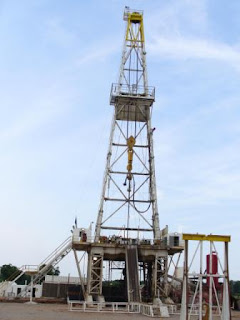
oil gas platform offshore

The pressure to reduce the cost of new developments has never been greater for North Sea operators. The combination of low oil prices, decreased North Sea development opportunities and increased competition from the U.S. shale industry means the industry is being forced to adapt to new ideas.

One development concept that is starting to gain traction is the use of low-cost wellhead platforms for the development of small satellite fields. These are typically newly discovered fields close to an established host platform, which can provide control and power and also carry out fluid processing. Although wellhead platforms have long been a favorite in the shallow waters of the southern North Sea, up until now the preferred option for the development of satellite fields in deeper water has been to use a subsea manifold with a tieback to the host facility. Subsea manifolds are tried, tested and trusted, but WorleyParsons has carried out several studies showing that subsea manifolds don’t necessarily provide the best value solution for a multiple well development. The difficulties and additional costs associated with maintenance and future well intervention operations can all contribute to increased costs over the lifetime of a project.

WorleyParsons has accumulated a reference list of more than 500 installations that are currently operating throughout the world, and its team has combined its experience with ideas borrowed from the shale industry—where standardization and modularization of equipment is the key to low-cost field development. The company has come up with a new concept in wellhead platforms suitable for installation in deeper water and able to withstand North Sea conditions.

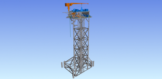
The new design uses piled foundations, can be deployed in water depths of up to 120 m (394 ft) and provides space for a maximum of 12 well slots. No accommodation has been provided for personnel, who will gain access for four monthly maintenance visits by vessels equipped with a “walk-to-work” gangway. The platform design includes a 5-tonne crane and sufficient deck space to allow full access for future well intervention. WorleyParsons also has designed the new platform for construction in its covered yard near Stavanger, Norway, with one flat side to permit installation by either barge launch or jackup platform to widen the choice of installation contractor.

The platform is designed with a “design once, build many” approach to capture economies of scale and efficiencies more closely associated with a production line than a North Sea construction yard. The design borrows from the philosophies that WorleyParsons has previously followed in the Persian Gulf and Gulf of Thailand and uses a minimum number of different profiles to reduce procurement and stockholding costs.

Topsides and jacket weights are comparable to more traditional North Sea designs at about 650 tonnes and 3,500 tonnes, respectively, for a 100-m (328-ft) water depth platform, with almost all of the topsides and much of the jacket being identical for any platform regardless of water depth. However, there is scope for significant savings in project schedule by both reducing setup times and by allowing construction to start in parallel with detailed design. The design is so standardized that water depth, seabed conditions and well slot arrangement are the only pieces of information required to completely define an individual platform, further reducing project schedule and minimizing construction risk.

WorleyParsons sees an immediate market for at least 20 lowcost modularized platforms in the Norwegian sector of the North Sea alone and is talking to several operators who have been carrying out studies to assess their viability. They also see applications in U.K. waters, where the upcoming 30th licensing round will be targeting small pool discoveries that will require especially low-cost development schemes.
Read MoreNew Platforms Design Withstand North Sea Conditions

Optimizing Artificial Lift Through Enhanced Control Systems


Canada is the world’s fifth largest oil producer. This is due in large part to the country’s vast reserves in and around Alberta, which contains the third-largest known oil reserves in the world.

Calgary-based ARC Resources Ltd. has called this oilrich region home for more than 20 years. The company has assets distributed across western Canada and operations that include E&P and development of conventional oil and natural gas.

Just across Alberta’s western border in northeast British Columbia, ARC Resources is one of the largest operators in the Montney region, which is considered one of the best tight gas plays in North America. And it was here that ARC Resources recently decided to begin optimizing the control systems it was using for its large multiwell natural gas production sites. The existing systems in place at these sites didn’t support artificial lift, which would soon be needed to maintain production levels. The systems also presented both expansion and safety challenges that the company wanted to address.

Operations at a crossroad

ARC Resources already had optimization programs at its smaller pads that contained only one to four wells. Control systems in place at these pads supported the use of artificial lift systems to help maintain or increase production as these wells depleted.

Larger pads of five or more wells, however, lacked control systems to support artificial lift systems. As some of these sites approached production milestones of 10 to 15 years, the company knew that it would need to make improvements in the near future.

“We were very successful with using assisted lift to keep production stable in the smaller fields,” said Charlie Kettner, programming specialist for ARC Resources. “We didn’t have the same optimization option in our bigger pads. So our production engineers wanted to find a control solution that would allow us to bring artificial lift to these fields as well.”

The existing controllers were not capable of handling the large amount of integrated operations required to run the entire well pad. As a result, the company had to use multiple controllers hardwired together along with remote terminal units (RTUs). This approach not only made the control infrastructure more complex and thus more prone to mistakes but also limited the amount of information available for control and monitoring.

The use of multiple hardwired controllers also presented safety challenges. ARC Resources relies on its control architecture to monitor toxic and explosive gases and to take actions such as turning on an exhaust fan or blocking wells as conditions dictate. But the controllers could lock up and freeze their outputs and give no indication that there was a fault. This forced the company to add “watch dog” timer hardware to monitor for such conditions.

A ‘canned package’

Kettner reached out to Rockwell Automation to begin discussions about optimization options that would support artificial lift systems at the large multiwell pads as well as simplify control and address safety concerns.

Their talks led them to the ConnectedProduction well manager system from Rockwell Automation, which includes an out-of-the-box Allen-Bradley ControlLogix programmable automation controller (PAC) and FactoryTalk View human-machine interface that requires no custom coding. The PAC gives ARC Resources single-platform control for large sites with up to 32 artificial lift wells and contextualized production information to help operators maintain optimal production levels and troubleshoot issues.

“It’s a canned package,” Kettner said. “You order it, install it and plug in your data to the points it’s looking for, and away you go.”

Kettner and his team decided to pilot the new technology at an eight-well production site named Sunrise near the town of Dawson Creek, British Columbia, before installing it at four other multiwell pad sites.

One of the benefits they first discovered during this trial run was the add-on instructions included in the ConnectedProduction, which helped them save about two days of programming during the installation process. Because the technology uses an open architecture, integration with other vendor hardware at the site was easy.

Enhanced visibility and safety

ConnectedProduction has eliminated the need for multiple controllers and RTUs that were previously in place at the Sunrise site. Now all well pad controls have been consolidated into a single control platform. In addition to simplifying the architecture, this will help lower hardware and software costs for the site.

The system also enables the use of artificial lift systems, including on/off timers and plunger lift systems, and provides visibility into those systems.

“Operators can track events in the Connected- Production solution to see what stage we’re in of the optimization cycle and make better decisions about what to do next,” Kettner said. “Operators can see, for example, that a timer well is not producing anymore and move to the next step of putting a plunger in the hole.”

The new system also is helping ARC Resources enhance safety by reducing the risk of faults going undetected at the Sunrise site.

“Now if something goes wrong with the processor, or if an I/O [input/output] rack comes undone, the ControlLogix platform can fault to a safe state where it shuts down all the processes,” Kettner said. “It takes all the power off the solenoids and essentially results in an emergency shutdown.”

Another benefit of the ConnectedProduction system is that it can support a flow-measurement card within the control panel. This has allowed Kettner to eliminate the use of a separate flow-measurement computer, which is saving his company tens of thousands of dollars at the site.

“We just plug the card into the rack, and it communicates on the backplane,” Kettner said. “It’s given us huge cost savings.”

Looking ahead, Kettner already has orders in to bring the ConnectedProduction system to at least four more large multiwell pads in the area.

“We’ve seen the value of the Rockwell Automation solution and want to bring it to our other sites where we need assisted lift,” he said. “On new pads we’ll implement this right from day one so it’s there and available when it’s needed. And we can just turn it on.”
Read MoreOptimizing Artificial Lift Through Enhanced Control Systems

Reduced Tubing Wear with Coupling


The economic landscape of the oil and gas industry has shifted and, as a result, operators in U.S. shale plays are increasingly looking for ways to streamline their practices and boost profitability. Coming to grips with production costs is crucial in the $50/bbl environment, and every component used in production should be scrutinized to assess if changes and improvements can be made to reduce wastage, costs and time lost on the well.

For example, nearly all of the wells operating in U.S. shale fields require artificial lift, and nearly half of those wells experience failure as a result of couplings contacting the inner tube wall, which creates friction that leads to considerable wear and damage. These failures are both hazardous and costly, running into the tens of thousands of dollars per well per year. Across the industry workover costs account for hundreds of millions of dollars per year.

To come up with an efficient, more cost-effective solution for well workovers, Materion Corp. partnered with Hess Corp. to develop and field test stronger, more fatigue-resistant sucker rod couplings made of ToughMet 3 TS95 alloy.

Materion developed a new temper of its ToughMet 3 alloy specifically to address the challenges of coupling on tubing wear. This copper-nickel-tin spinodal alloy was originally engineered by Materion for use in drilling equipment. Offering high strength and low friction, this alloy demonstrates corrosion and corrosion-related stress cracking resistance in seawater, chlorides and sulfides.

With its combination of properties, this alloy resists mechanical wear, thread damage, corrosion and erosion. The couplings are non-galling, so they do not damage production tubing, and they retain their strength even at elevated temperatures.

Bakken-tested

Materion partnered with Hess, one of the largest producers in the Bakken, to qualify and pilot the ToughMet sucker rod couplings in deviated wells with higher than normal failure rates. Hess noted that the couplings more than tripled the mean time between failures associated with couplings made of alternative materials.

Encouraged by the results observed in the field tests, the company installed the couplings in more than 400 of its Bakken wells and now uses the couplings as part of its standard production practice.

Materion is expanding the deployment of its ToughMet couplings with additional operators in several different shale plays. Now about 20 operators are running the couplings in the Bakken and Permian and in the Elk Hills Field in California. To facilitate access to the couplings for operators, Materion is establishing distributors in each of these regions so that the couplings are available from local inventory.

Permian perspective

Discovery Natural Resources LLC is a private oil and gas company that operates more than 1,000 wells in the Permian Basin. To date, the company has used the ToughMet couplings in about 20 wells in the Permian and is seeing positive results.

Discovery owns some wells that were failing every 60 to 90 days, specifically due to rod-on-tubing wear as a result of extreme deviation. The company piloted the ToughMet couplings as a solution and as a result significantly increased the run time on those wells.

Discovery reported that its longest running well with these couplings is more than 385 days without a failure. The company has four additional wells with the couplings installed that are past the 300-day mark. In addition, Discovery has doubled or tripled its run times.

Discovery pulled the rods out of one of the ToughMet test wells after a pump failure and inspected the couplings after three months of the well running. It would typically see significant tubing or coupling wear after this period in the ground but saw that the original stencils from the manufacture were still visible on the coupling (see image above). There was minimal wear observed on the couplings. For Discovery that was an early indication that the couplings reduced rod-on-tubing wear.

Sucker rod pumping in long deviated unconventional wells is especially challenging because of side-loading of rods. Sucker rods can buckle due to forces acting in compression at the bottom of the rodstring on downstroke.

If rod side loads are calculated at more than 100 lb, Discovery considers running ToughMet couplings in that area to increase the run time on that particular well. The company reported that ToughMet is becoming increasingly well-established in its operations. Now that the test phase is completed, the company is using more ToughMet couplings.

By utilizing a sucker rod coupling that actively mitigates coupling-on-tubing wear, operators are helping reduce downtime and improve production efficiencies by eliminating the need for more frequent workovers.
Read MoreReduced Tubing Wear with Coupling

Friday, December 1, 2017

Cellar Purpose in Oil Gas Drilling Onshore


Before We talk about what is Cellar or Cellar purpose, I will mention from rig located in new well location.

Once the site has been selected, scientists survey the area to determine its boundaries, and conduct environmental impact studies if necessary. The oil company may need lease agreements, titles and right-of way accesses before drilling the land. For off-shore sites, legal jurisdiction must be determined.

After the legal issues are settled, the crew goes about preparing the land:

The land must be cleared and leveled, and access roads may be built.

Because water is used in drilling, there must be a source of water nearby. If there is no natural source, the crew drills a water well.

The crew digs a reserve pit, which is used to dispose of rock cuttings and drilling mud during the drilling process, and lines it with plastic to protect the environment. If the site is an ecologically sensitive area, such as a marsh or wilderness, then the cuttings and mud must be disposed of offsite -- trucked away instead of placed in a pit.

Once the land has been prepared, the crew digs several holes to make way for the rig and the main hole. A rectangular pit called a CELLAR is dug around the location of the actual drilling hole. The CELLAR provides a work space around the hole for the workers and drilling accessories. The crew then begins drilling the main hole, often with a small drill truck rather than the main rig. The first part of the hole is larger and shallower than the main portion, and is lined with a large-diameter conductor pipe. The crew digs additional holes off to the side to temporarily store equipment -- when these holes are finished, the rig equipment can be brought in and set up.

Depending upon the remoteness of the drill site and its access, it may be necessary to bring in equipment by truck, helicopter or barge. Some rigs are built on ships or barges for work on inland water where there is no foundation to support a rig (as in marshes or lakes).

Read MoreCellar Purpose in Oil Gas Drilling Onshore

General Step and Procedure Oil Gas Drilling in Onshore


To find oil, you cannot simply punch a hole in the ground. Perhaps, this is what many people believe.
There are many complexities involving multiple service companies and two complete teams of crews. With so much happening (and with so many difficulties regarding scheduling, safety, and environmental practices) drilling for oil is not for the faint of heart.

This is a general 51 steps for drilling in the USA, for example. 

The following steps are necessary in order to produce oil or gas from a well:
  1. 10-30 different service companies are required.
  2. Each company working on a well must adhere to around-the-clock scheduling, safety and environmental practices.
  3. Build a new road to access the rig location.
  4. Clear the area for the new rig.
  5. Build infrastructure for water and electricity around the rig site.
  6. Dig an earthen pit to prevent soil or water table contamination.
  7. Dig a pilot hole at the precise location marked by the survey crew.
  8. Dig two other holes (the “mouse” hole and the “rat” hole) nearby to hold pieces of equipment and pipe during drilling.
  9. A rig that can dig a 10,000 ft. well requires 50-75 people and 35-45 semi-trucks to move and assemble the rig.
  10. Assembly of the rig takes around 3 and a half days.
  11. A strict inspection of the rig must take place once built.
  12. Operations of the rig go on 24/7, typically ceasing only one day each year for Christmas.
  13. Two shifts of two complete crews must work the rig every day.
  14. There are two stages of drilling: 1. running and cementing of cases and 2. drilling until the bit reaches the depth of the targeted zone.
  15. Each drill bit typically lasts 4,500 – 6,500 feet of drilling.
  16. Replacing the bit requires the removal of the entire string of drill pipe in a process called “tripping out”.
  17. “Tripping out” takes several hours and requires crews to cool the bit and keep the soil and hole intact.
  18. To help keep cuttings from plugging the hole, the mud must be sent through shakers to send the cuttings into a separated area.
  19. Additional mug system equipment: de-sanders, de-silters and de-gassers, remove smaller particles and gas from the mud.
  20. Clean mud is then recirculated back down into the hole.
  21. The Blow-Out Preventer (or “BOP”) is installed on top of the casing head before drilling takes place.
  22. The BOP must have high-pressure safetly valves designed to seal off the well and block any escaping gases or liquids from the hole beneath in order to prevent a blow-out from occuring.
  23. Drilling must begin with a designated surface depth, usually around 50-100 feet below the water table.
  24. Special care must be taken to prevent contamination of the water in the water table while drilling by isolating the water table and the wall with concrete and steel encasing.
  25. New sections of pipe must be added to the string as the bit drills deeper.
  26. When the hole reaches a designated depth, the derrickhands secrete fluid through the hole to condition it for logging.
  27. A “logging tool” measures the depth and condition of the hole for the oil company.
  28. The tool gives the information of whether or not the well can indeed produce oil or gas.
  29. At this point, it must be determined whether the well is to be complete or plugged and abandoned.
  30. If the well is designated as a producer, the crew must re-insert the pipe back into the hole to ensure the hole is still intact.
  31. To test the hole, mud must be re-circulated.
  32. Once everything tests positively, the drill pipe is removed.
  33. At this point, the crew must insert the last string of production casing running the entire depth of the hole.
  34. Then, the casing is cemented in the hole.
  35. The production crew then brings in the work-over unit and rigs it up to prepare the hole for production.
  36. The crew runs small diameter tubing into the hole as a conduit for oil or gas to flow through and up the well.
  37. Next, the work over unit trips out of the hole and picks up a perforating gun.
  38. The perforating gun is lowered into the hole to production depth using a thin metal cable called a “wireline”.
  39. An electrical signal is sent down the wireline, firing the gun and igniting explosive charges.
  40. These charges create holes through the cement encasing and formation connecting the well bore to the reservoir.
  41. To stimulate the flow of hydrocarbons (or oil), sometimes it’s necessary to “frack” the well.
  42. “Fracking” involves pumping air, sand and fluids under extreme pressure down the hole and out through the perforations.
  43. This fractures or forces cracks into the formation.
  44. The remaining particles will hold the cracks open, releasing the flow of oil or gas.
  45. Monitoring the flow allows the crew to determine the best location for the “choke”.
  46. The “choke” controls the flow of the oil or gas.
  47. Once pressure is released, the hydrocarbons are allowed the escape through the fractured zone and flow into the well bore.
  48. The oil or gas can now travel up the well casing string.
  49. The well bore is isolated from the surrounding formations with casing and cement, preventing any contamination.
  50. The final step is to install a pump jack or production well-head, or what’s called the “Christmas Tree”.
  51. It’s the time to produce the well and plan for any future field development.
Watch the Video : 


Read MoreGeneral Step and Procedure Oil Gas Drilling in Onshore

Thursday, November 30, 2017

Big Shale Technology

oil gas well drilling

Shale oil engineer Oscar Portillo spends his days drilling as many as five wells at once— without ever setting foot on a rig.
Part of a team working to cut the cost of drilling a new shale well by a third, Portillo works from a Royal Dutch Shell Plc office in suburban Houston, his eyes darting among 13 monitors flashing data on speed, temperature and other metrics as he helps control rigs more than 805 km (500 miles) away in the Permian Basin, the largest U.S. oil field.
For the last decade, smaller oil companies have led the way in shale technology, slashing costs by as much as half with breakthroughs such as horizontal drilling and hydraulic fracking that turned the United States into the world’s fastest-growing energy exporter.
Now, oil majors that were slow to seize on shale are seeking further efficiencies by adapting technologies for highly automated offshore operations to shale and pursuing advances in digitalization that have reshaped industries from auto manufacturing to retail.
If they are successful, the U.S. oil industry’s ability to bring more wells to production at lower cost could amp up future output and company profits. The firms could also frustrate the ongoing effort by OPEC to drain a global oil glut.
“We’re bringing science into the art of drilling wells,” Portillo said.
The technological push comes amid worries that U.S. shale gains are slowing as investors press for higher financial returns. Many investors want producers to restrain spending and focus on generating higher returns, not volume, prompting some to pull back on drilling.
Production at a majority of publicly traded shale producers rose just 1.3%over the first three quarters this year, according to Morgan Stanley. But many U.S. shale producers vowed during third-quarter earnings disclosures to deliver higher returns through technology, with many forecasting aggressive output hikes into 2018.
Chevron Corp. is using drones equipped with thermal imaging to detect leaks in oil tanks and pipelines across its shale fields, avoiding traditional ground inspections and lengthy shutdowns.
Ryan Lance, CEO of ConocoPhillips—the largest U.S. independent oil and gas producer—sees ample opportunity to boost both profits and output. ConocoPhillips also oversees remote drilling operations in a similar way to Shell.
“The people that don’t have shale in their portfolios don’t understand it, frankly,” Lance said in an interview. “They think it’s going to go away quickly because of the high decline rates, or that the resource is not nearly that substantial. They’re wrong on both counts.”
Shell, in an initiative called “iShale,” has marshaled technology from a dozen oilfield suppliers, including devices from subsea specialist TechnipFMC Plc that separate fracking sand from oil and well-control software from Emerson Electric Co., to bring more automation and data analysis to shale operations.
One idea borrowed from deepwater projects is using sensors to automatically adjust well flows and control separators that divvy natural gas, oil and water. Today, these subsea systems are expensive because they are built to operate at the extreme pressures and temperatures found miles under the ocean's surface.
Shell’s initiative aims to create cheaper versions for onshore production by incorporating low-cost sensors similar to those in Apple Inc.’s Watch, eliminating the need for workers to visit thousands of shale drilling rigs to read gauges and manually adjust valves. Shell envisions shale wells that predict when parts are near mechanical failure and schedule repairs automatically.
By next year, the producer wants to begin remote fracking of wells, putting workers in one place to oversee several projects. It also would add solar panels and more powerful batteries to well sites to reduce electricity and diesel costs.
Oil firms currently spend about $5.9 million to drill a new shale well, according to consultancy Rystad Energy. Shell expects to chop that cost to less than $4 million apiece by the end of the decade.
“There is still very little automation,” said Amir Gerges, head of Shell's Permian operations. “We haven’t scratched the surface.”
Technology, Geology
Much of the new technology is focused on where rather than how to drill.
“There is no amount of technology that can improve bad geology,” said Mark Papa, CEO of shale producer Centennial Resource Development Inc.
Anadarko Petroleum, Statoil and others are using DNA sequencing to pinpoint high potential areas, collecting DNA from microbes in oil to search for the same DNA in rock samples. ConocoPhillip’s MRI techniques also borrow from medical advances.
ConocoPhillips next year will start using magnetic resonance imaging (MRI) to analyze Permian rock samples and find the best drilling locations, a technique the company first developed for its Alaskan offshore operations.
EOG Resources Inc. last year began using a detailed analysis of the oil quality of its fields. The analysis, designed by Houston start-up Premier Oilfield Laboratories, helps to speed decisions on fracking locations and avoid less productive sites.
Premier has reduced the time needed to analyze seismic data to find oil reserves from days or weeks to seconds. Such efficiencies serve two purposes, said Nathan Ganser, Premier’s director of geochemical services.
“It’s not only removing costs thatare superfluous,” he said. “It’s boosting production.”
Read MoreBig Shale Technology

Tuesday, November 28, 2017

What worker doing during Drilling Operation?


During drilling, the personnel and equipment must be protected against unexpected pressure surges in the wellbore. In oil and gas drilling, these surges can come from hydrocarbon fluids trapped under impermeable rock which holds them at pressures higher than the static head of the fluid column in the wellbore, and in geothermal operations the surges come from hot formations which heat the pore or wellbore fluids above the saturation temperature at the static wellbore pressure. In either case, the first line of control is the weight of the fluid column in the wellbore. 

With a gas column, this weight is negligible, but with mud the liquid density will range from slightly greater than water (-8.5 pounds per gallon) to almost three times that. In addition to the clays and additives which raise the viscosity of the mud to improve hole cleaning, weighting materials such as barite are often added to increase the mud's density and enable it to control higher downhole pressures.

The pressure surge cannot immediately be controlled with fluid weight, the wellbore can be mechanically sealed at the surface with BOPS, or blow-out preventers. There are three principal types of BOP: blind rams, which are sliding plates that come together across the wellbore when the drill string is not in the hole; pipe rams, which are like blind rams except that the sliding plates are cut out in the center so the rams can seal around the drill pipe; and an annular preventer, which is an inflatable bladder that seals around drill collars, stabilizers, or other off-size or irregularly shaped tools.

Read MoreWhat worker doing during Drilling Operation?

Geothermal Drilling with Kelly Rig


To make the hole or drilling well with kelly rig, energy must be transmitted from the surface to the rock face at the end of the wellbore. Power supply for drilling has evolved from the early days of steam-driven,mechanically coupled rigs to the current standard of diesel-electric drive. In this configuration, two to four diesel engines (up to 2,000 horsepower each) drive electric generators, which supply power to individual electric motors driving the rotary table, drawworks, mua pumps, and other equipment. The rotary table is a mechanism, usually inset into the rig floor, which turns the drill string to break rock and advance the hole. (A "drill string" comprises the drill pipe plus the bottom-hole-assembly, or BHA. The BHA includes drill collars, stabilizers, bit, and any other specialized tools below the drill pipe).

Hole diameters in oil and gas drilling usually range fiom 4 to 26 inches, while geothermal holes generally have a minimum production size of 8-112 inches. To drill these holes, torque is applied to the kelly, which is at the top of the drill string. The kelly is a section of pipe with a square or hexagonal outside cross-section which engages a matching bushing in the rotary table. This bushing lets the rotary table continuously turn the kelly and drill string while they slide downward as the hole advances.

The upper end of the kelly is attached to a 'hvivel", which is a rotating pressure fitting that allows the drilling fluid to flow fiom the mud pumps, up the standpipe, through the kelly hose, into the swivel, and finally down the drill pipe as it rotates. The swivel is carried by the hook on the traveling block and it suspends most of the weight of the drill string while drilling.

Moving the drill string or the casing into and out of the hole is called tripping. Trips are usually required because the bit or some other piece of downhole equipment must be replaced, or because of some activity such as logging, testing, or running casing, and of course trips take longer as the hole grows deeper. Raising or lowering the drill string for a trip is done by the drawworks, which is basically a large winch. (The swivel and kelly are almost always handled as a unit, and are set aside in the "rat hole" while tripping.) The drawworks reels in or pays out a wire rope (drilling line) which passes over the crown block at the top of the rig's mast and then down to the traveling block which carries the hook, which in turn suspends the drill string or casing. Depending on what mechanical advantage is required, the drilling line is reeved several times between the crown and traveling blocks, as in a block and tackle.


Read MoreGeothermal Drilling with Kelly Rig

Preperation Drilling Operation

oil gas well drilling

In the baseline system, all of the equipment necessary for the drilling operation is organized around the derrick, or mast. This is a steel tower , ranging from 50' to 180' in height, which supports the drill pipe with the bit and all the other downhole equipment, and which provides a platform for much of the other equipment necessary to drill the hole. 

Every rig, except for the smallest ones, has a floor just above ground level where most activity required to operate the rig takes place. The driller, who has minute-by-minute control of the rig's operation, has a console here and most pipe handling (adding a new piece of pipe, making and breaking drill string connections, changing bits, etc.) takes place on the floor. In smaller rigs, the mast and the floor are a unit and are simply raised into position in preparation for drilling. 

Bigger rigs, which may require 50 to 60 large truck loads for transportation, are usually assembled at the drill site, a job which may take s e v d days, even in accessible locations on land. offshore, or in locations with difficult access, this assembly is much more complex and time-consuming. Eventually the mast will be erected, the power generation system on-line, the fluidhandling equipment plumbed together, and the myriad other smaller components in place; only then is the rig ready to begin drilling a hole 
Read MorePreperation Drilling Operation

New drilling technologies could give us so much oil

drilling oi gas  new technology

New oil drilling technologies could increase the world’s petroleum supplies six-fold in the coming years to 10.2 trillion barrels, says a report released today by market research firm Lux Research.

The most common and controversial technique is hydraulic fracturing, or fracking, in which chemical-laced water is injected to break up subterranean rock formations to extract oil and natural gas. But the Lux report details a host of exotic so-called Enhanced Oil Recovery (EOR) technologies—from solar-powered steam injection to microorganisms—that could be used to extend the life of old oil fields and gain access to so-called unconventional petroleum reserves like oil sands.

“In light of current oil prices, the peak oil hysteria and projection of $300 [a barrel] prices of a few years ago seem overblown – if not outright silly,” the report states. “But in a sense, they were accurate forecasts of what would have happened if EOR technologies had not come online and made unconventional oil reserves – which vastly exceed conventional ones – accessible.”

But don’t ditch your electric car just yet. The development of such technologies is predicated on high oil prices – at least $100 a barrel – to offset the costs and induce a conservative industry to invest in and deploy new methods. And many of the technologies are still young.

Moreover, as we’ve seen with fracking, political opposition to technologies that could pollute the environment and use lots of water could derail their use. And as climate change accelerates, opposition to carbon-intensive extraction of fossil fuels and their expanded use is sure to grow.
Still, here are some of the technologies startups and multinationals alike are pursuing:

Thermal intervention injects steam into wells to extract heavy oils or oil sands. The problem is, it takes a lot of energy to generate that steam, so some oil companies are turning to solar energy instead of natural gas or other fossil fuels. Chevron, for instance, has deployed solar fields built by BrightSource Energy and GlassPoint Solar at old oil fields in California to help recover heavy petroleum.

Chemical EOR injects polymers and alkaline compounds into oil fields to help loosen oil from rock formations and push it into production wells. The China National Petroleum Corporation is the leader in this method, which it is betting will be 20% more efficient than just flooding wells with water to bring oil to the surface. But in the US, expect opposition to introducing large volumes of chemical underground anywhere near water supplies. Some other drawbacks: Chemical EOR doesn’t work well in oil reservoirs where temperatures are high and there’s a lot of salt and sulfur.

Microbial EOR uses environmentally benign microorganisms to break down heavier oils and produce methane, which can be pumped into wells to push out lighter oil. The technology dates from the 1950s but only recently has it been put to limited use. An experiment with microbial EOR in Malaysia, for instance, increased oil production by 47% over five months. But oil and gas engineers are not biologists, the report notes, and may be reluctant to embrace the technology.
Read MoreNew drilling technologies could give us so much oil

New Oil Drilling Technology Will Soon Spark An Explosion Of Oil


Energy stocks have been tearing higher since the election on bets that the Trump administration will relax environmental restrictions and open more federal lands to oil and gas drilling. Crude oil’s staying north of $50 hasn’t hurt, either.

It is up there in part because OPEC threw in the towel and agreed to production limits. Unfortunately for OPEC, those limits don’t apply to US and Canadian shale producers. And the history of OPEC is that they all cheat like crazy, anyway.

There will be no end to oil production

I think it is entirely possible that we will see oil prices climb somewhat further by mid-year, possibly approaching $60, and then pull back as capped US production comes back online. Look at the chart below to see the wide variation among forecasts of major energy analysts working for the big banks.


I also think that this year, we’ll start to see a new pattern: Production could keep rising even as prices fall. Conventional wisdom says that producers stop pumping at some point when it becomes unprofitable, but I think that is about to change.

New technology will lead to greater production and higher profits

If you are an oil producer—or really, any commodity producer—two things can improve your profit margin: higher selling prices for the resource you produce or lower production costs. Some combination of both works as well.
Now, selling prices are mostly outside the producer’s control, though adept hedging can help. Cost reduction is, therefore, the place to concentrate your attention. Back in 2015, I wrote about new drilling techniques and other technology that promised to bring oil and gas production costs significantly lower.

Now, in the last few weeks, people in the business have told me these technologies are moving rapidly toward deployment. They foresee considerably lower drilling and production costs by the end of this year.

I had a confidential briefing recently about some new energy production processes that are coming online in the oil patch. Let me just say that production from an oil well drilled with these new techniques is getting ready to increase substantially.

In some cases, the amount of oil produced per dollar spent on drilling is going to more than double. There are significant chunks of the petroleum-producing parts of the United States where $40 oil will not be a barrier to drilling and new production.

Eventually—in a few years—these techniques will begin to show up in wells around the world, and there will be an explosion of oil. Even as many oilfields dry up, there will be new fields developed from previously unprofitable sources.

This will have massive economic and geopolitical implications

This technology trend means that the current oil price range may well break lower—perhaps this year, but certainly within this decade—without energy companies losing profits.

Not every company will reap the rewards equally, of course; but the industry as a whole is excited. Energy exploration and production is quickly becoming a technology-driven industry with the US as world leader.

If Trump permits construction of more pipelines and natural gas export terminals, we could see North American exports rise considerably in the next few years.

Obviously, over time, a falling energy price will not be good for OPEC or for Russia. Those lower prices will create geopolitical challenges as well as economic ones. I don’t know how it will all shake out. We will likely see some big, energy-driven changes in the world order in the coming decades.

But that is beyond the scope of my crystal ball.

Source: www,forbes.com
Read MoreNew Oil Drilling Technology Will Soon Spark An Explosion Of Oil

Well’s Production prediction with Microseismic Technology

drilling technology

With efficiency being crucial when every dollar counts, operators in unconventional plays could add microseismic technology to fracture modeling methods to gain insight into permeability advances and better forecast production.

That’s according to Sudhendu Kashikar, vice president of completions evaluation for MicroSeismic Inc.

Understanding drainage volume and improved permeability of stimulated rock are essential to forecasting production, he said. Typically, several models are used to accomplish this, but the approach has its drawbacks.

A single frack model per stage ignores geological variations along the wellbore. Plus, a discrete fracture network (DFN) model is needed to determine how fracturing actually improves the permeability of stimulated rock, Kashikar said.

Microseismic techniques can simplify the workflow and help with production forecasting, Kashikar said during a webcast June 16.

“Technology and procedures were developed to discriminate the microseismic events and fractures described by these events, capturing propped versus unpropped fractures,” Kashikar said while describing Productive-stimulated rock volume (Productive-SRV) technology. “A rock volume capturing the proppant-filled refractures showed much better correlation to the cumulative production than the total stimulated rock volume.”

Productive-SRV technology estimates how much stimulated fracture remains open through proppant placement by using estimated target zone productivity, a DFN, propped fracture estimate and the Fat Fracture drainage estimate, according to MicroSeismic’s website.

Focus is usually on the location of the proppant, but focus should also be on the amount of improved permeability achieved within the SRV or the Productive-SRV, he said.

Understanding and measuring such improvements will lead to the next step in reservoir stimulation and production forecasting, he said.

Using microseismic data has proven beneficial in establishing a deterministic DFN, which shows fractures detected through seismic.

“For every microseismic event we describe a fracture plane. The size is guided by the magnitude, and the orientation comes from the focal mechanism,” he said. “This is much easier to do with surface microseismic.”

The model is calibrated to actual fluid volumes pumped for a well. A mass balance approach is used to fill the fractures with proppant starting from the wellbore moving outward until the proppant is consumed for that stage, Kashikar explained. Once the fracture network and the propped network have been established, a geocellular grid can be superimposed to obtain the SRV and productive SRV to capture the proppant-filled rock volume, he said.

“One advantage of this workflow is the ability to capture fracture intensity—the number of fractures, the orientation of these fractures—to quantify the permeability enhancement achieved,” Kashikar added.

Key steps for the production forecasting workflow are describing three reservoir volumes—the productive SRV (the propped fractures), total SRV (includes propped and unpropped fractures) and the permeability scalar for individual cells within each region to determine how permeability improved for neighboring cells.

This workflow, he said, captures not only the size and shape of the drainage volume but also permeability within the drainage volume.

The process is a big step forward, he said, in understanding and determining the effectiveness of hydraulic fracturing.

“Rather than relying on a single representative fracture model, we can fully and accurately capture the variable fracture geometry and fracture intensity for the entire length of the wellbore, providing a much better production forecast,” Kashikar said. “We can now use the productive stimulated rock volume and the stimulated rock volume with permeability scalars to directly and explicitly describe the reservoir volume in the reservoir simulator.”

Source: www.epmag.com
Read MoreWell’s Production prediction with Microseismic Technology

Monday, November 27, 2017

Drilling with Coiled Tubing for Multilateral Wells

The petroleum industry is constantly driving to reduce capex and increase economic recoverability while minimizing environmental impact and surface footprint. By combining the three advanced drilling techniques of multilateral drilling, underbalanced drilling (UBD) and directional coiled tubing drilling (CTD), an operator can capture significant value out of known reserves.

The highest well productivity is achieved through maximizing reservoir contact per well/surface slot and minimizing reservoir damage. Multilateral drilling reduces capex through drilling multiple reservoir sections per surface slot while also increasing reservoir contact per surface slot. UBD minimizes reservoir damage, which maximizes the productivity of each lateral. CTD is inherently set up for underbalanced operations (UBCTD), and CTD bottomhole assemblies (BHAs) can achieve high build rates of up to 50 degrees per 30 m (100 ft) to allow multiple targets to be accessed from the mother wellbore.

Selecting a BHA

A directional CTD BHA consists of a coil connector, cablehead, electric or mechanical disconnect, downhole orienter, sensor package, motor or turbine with a bent housing, and a drillbit. Drilling directionally on coiled tubing (CT) is similar to conventional slide-and-rotate drilling on a rotary. As CT cannot be rotated from surface, all the rotation needs to be carried out downhole through the orienter. The rotating orienter allows the toolface to be set from surface or for the motor to be rotated to drill a straight hole.

Service companies also can provide additional BHA modules such as a gyro module for orienting a whipstock and for drilling in the presence of magnetic interference immediately after exiting the casing.

CT drilling faces two fundamental challenges: transferring weight to the bit and length limitations of the lateral sections. If the well trajectory plans for high doglegs, then it can be difficult to transfer weight to the bit. This is accentuated by the inability to rotate the whole drillstring as in conventional drilling. It is essential to have a weight-on-bit (WOB) sensor in the BHA so the driller can see that the weight is actually being transferred to the bit and react accordingly. The length of laterals that can be drilled with CT also are affected by the tortuosity, but this is particularly true in horizontal sections. The more tortuous the wellbore, the shorter the lateral length will be. CTD BHAs that have a continuous rotating orienter prevent this tortuosity from occurring and therefore maximize the available WOB and lateral length (Figure 1).


FIGURE 1. A straight wellbore increases the potential length of a lateral section compared to a wavy wellbore. (Source: AnTech)


Designing a multilateral well

All well designs require a multidisciplinary team to be successful. When designing a multilateral well, an integrated team of subsurface specialists and directional drilling specialists is even more essential to successfully drill the well. The well design and completion strategy is heavily affected by the reservoir characteristics, horizontal and vertical permeability, the geological structure, and geosteering requirements. The first step is to clarify if significant productivity gains can be made from utilizing multilaterals over other techniques. Once established, it is an iterative process between the directional drilling contractor and the operator’s engineering and subsurface teams to find the best way to design the well.

There are a near-infinite number of wellbore paths for multilateral wells. The two most common are stacked laterals and forked laterals (Figure 2). Stacked laterals can access different layers of a laminated reservoir. Forked laterals are all at a similar depth and are most commonly used to increase reservoir contact in a specific formation. Clarifying the objective for the multilaterals early on helps reduce the number of iterations required of the trajectory.


FIGURE 2. Stacked laterals offer access to different layers of a laminated reservoir, while forked laterals are at a similar depth and help increase reservoir contact in a specific formation. (Source: AnTech)


Once the trajectories are drafted, the wells must be modeled to ensure drillability and to specify surface equipment. For the CTD section the main areas for analysis are the available WOB, CT lock-up limit, borehole cleaning and surface pressures. The CT can be specified from these models. Production and geomechanics models also must be run to ensure the separation equipment is suitably specified and the amount of the underbalance applied to the wellbore does not cause wellbore stability issues.

Sidetracking techniques

To create the additional well path from the mother wellbore, a sidetrack must be initiated. There are two main categories of sidetracking a well: cased-hole sidetracks and openhole sidetracks. The cheapest and fastest way to carry out a cased-hole sidetrack is to use a whipstock and a window milled in the casing rather than section milling.

Multiple whipstocks can be set in the mother wellbore and retrieved if required. For openhole sidetracks the drilling BHA is used to create a trough in an inclined section of the wellbore. Once the trough is initiated, the WOB can be increased to carry on the borehole section. An openhole sidetrack also can be initiated off a cement plug with special procedures.

Since CTD BHAs operate on wireline, this allows significant amounts of real-time data to be received from the BHA. This helps to speed up the sidetracking process because rather than relying completely on time drilling, the directional driller can see the WOB and torque-on-bit responses to each operation and optimize on the fly. This is the case with both openhole and cased-hole sidetracks. A special module is required to monitor the casing milling operations since the vibration levels are so high.

Geosteering

A multilateral will not provide a good return on investment if the laterals are not drilled into the target zones. The options for geosteering on UBCTD are relatively limited compared to a conventional LWD service. Gamma ray and resistivity are available on certain CTD BHAs. A biostratigraphy service also can be used to identify changing formations. The UBD package can provide a significant amount of data that can be used for geosteering and reservoir characterization while drilling. The large amount of additional information that can be gathered from the real-time downhole sensors and the UBD package, if used correctly as part of an integrated data acquisition and reservoir evaluation strategy, can remove the need for expensive LWD tools or wireline logs.

Drilling practices

Drilling on CT has been avoided in the past due to concerns over stuck pipe and borehole cleaning issues. When drilling reentry wells using CTD, the borehole size is usually closer to the BHA size than in conventional drilling. In addition, since the pipe is not rotated, a greater focus needs to be placed on good borehole cleaning practices. Every CTD project must be modeled and analyzed to ensure the well can be drilled successfully. When drilling the borehole sections, the real-time drilling parameters must be monitored to identify any indications of borehole problems. Drilling practices also are adapted to ensure the borehole is clean and free of ledges. For example, a short trip must be made at every 46 m (150 ft) to ream the borehole, and at every 91 m to 137 m (300 ft to 450 ft) a long trip back to the casing window must be made. Because the driller is able to see these changes in downhole conditions at surface, there is an opportunity to prevent these issues and optimize the uptime of the operation.
Read MoreDrilling with Coiled Tubing for Multilateral Wells

The Connection in Oil Gas Drilling with new Technology

NOV connection technology drilling rig

As the drilling landscape changes, an upturn in land factory drilling projects drives the need for efficient, high-performance products and technologies. NOV addressed the needs of this shifting market by developing the Delta line of rotary-shouldered drillpipe connections. These connections are stronger and more fatigue-resistant than other rotary-shoulder connections, and this allows a simplified threading procedure, which excludes the need for cold rolling, reducing the cost of maintenance and therefore lowering the total cost of ownership.

Performance-wise, the connection delivers on average 4% more torque than the XT connection. Using streamlined 130,000-psi tool joints, the Delta connection improves hydraulic performance by allowing the use of a larger-than-normal pipe body size. For example, 5½-in. drillpipe can be used to drill in the size of hole in which 5-in. drillpipe was previously used. This is made possible because the outside diameter of the tool joint is identical to the industry standard for 5-in. drillpipe (65⁄8 in.).


In addition to significant reduction in pressure losses, the connection also allows better borehole cleaning since fluid circulates at a higher velocity outside of the drillpipe. The stiffer pipe allows the drilling of a better quality hole.
The modified geometry of the Delta connection engages more threads at stab-in. This minimizes stabbing damage while also evenly distributing stress.

The deeper stab-in also reduces the number of turns necessary to make up the connection, increasing efficiency and reducing wear on the threads.

Compared to similar products, the Delta connection requires 50% fewer turns from stab to makeup. The connection saves time in that it can be spun in as little as four seconds, while XT connections typically require eight seconds.

This decreased connection time translates to increased cost-effectiveness and ease of use on the rig floor. Ease of use is further improved by a reduction in the minimum required tong-gripping distance from the box face. When other connections require a 2-in. tong-free area to prevent egging of the box connection, the Delta connection only requires ½ in. of tong-free area, giving drillers more flexibility in the positioning of the iron roughneck.

Reduced cost of ownership

One of the main objectives while developing this connection was to reduce the cost of ownership. NOV determined the best way to achieve that goal is to keep the connection in service and reduce the frequency of repair. Multiple design choices contribute to maintaining the Delta connection—and the joint of drillpipe that carries it—in the field while drilling. First, wider field inspection tolerances reduce the need for frequent repairs without compromising the connection’s performance. Second, a tolerance for pitting in the root of the less critical threads was established. Besides these inspection criteria changes, the geometry of the new connection reduces the material loss by 30% for face-and-chase repair operations.

This allows more recuts using the same tool joint tong space. The reduction of the tong-free area on the tool joint results in increased room for recuts given the same tool joint length. The total refacing amount has been increased by 50%, allowing additional refacing to take place before a recut is needed.

Best practices were developed by the company for its licensees in the shop environment for these recuts. These practices will result in less than a 1-in. loss on pin or box for a full face-and-chase repair. The connection also has the lowest royalty on repair services across all of NOV’s double-shoulder connections. The Tuboscope Business Unit within NOV Wellbore Technologies further supports the connection with reduced repair rates to pipe owners and the option to include the TracID radio frequency identification-based tagging and inventory management system as part of the base configuration for the pipe connection. In support of the Delta connection NOV developed rig-ready upgrades such as the TDS-11SAH top drive, ST-80X iron roughneck and a 7,500-psi pump.

Before its introduction to market the Delta connection underwent extensive testing at NOV’s research and technology development center, with early results demonstrating that the new connection made up twice as fast as its predecessor. During testing, damage was minimal and was primarily related to handling. Generally, only refacing was required to repair the damage.

Case studies

The first string of drillpipe with the Delta connection was used to drill a well in the Permian Basin and was the subject of intense scrutiny. This initial drilling job was very successful, and the 5½-in. drillpipe with the Delta 544 connection delivered as expected. The drilling project finished ahead of schedule, and the hole quality of this longest lateral for the operator in this field was excellent, with smooth running of the casing string. A post-use visual inspection of the connections was conducted and confi rmed that the Delta string was in excellent condition after drilling the well. The rental string was retained by the operator and will be used again to drill another pad.

Two other strings with Delta 544 connections were deployed in April 2017, one in the Gulf of Mexico (GoM) and another on a land rig in West Texas. Once again, the customers found the product easy to use, and the field service personnel who were dispatched to these rig sites could see that drillers quickly became comfortable with the new connection.

In June the different sizes of the Delta connections were used on land and offshore. The Delta 425 on 4½-in. drillpipe was used in the GoM, South Texas and the Bakken Shale. Field service staff went to the rig site and saw the same pattern repeated: ease of use, low damage rates and satisfied end users. Drilling crews were at ease with the product and rapidly embraced its use. In addition, a string has been deployed to the Middle East for testing.

In all cases, the condition of the connection was visually evaluated after use, and so far none have required rethreading. This is extremely encouraging to the early users, and NOV looks forward to gathering more data once these strings have received a full visual and dimensional inspection of the Delta connections.
Read MoreThe Connection in Oil Gas Drilling with new Technology

Optimize Wells with Rotary Steerable Systems


Drilling technology by Schlumberger
In any well delivery operation there are three drivers—drilling efficiency, accurate well placement and high-quality wellbores.

The main objective in directional drilling is to accurately position the well within the target to optimize returns. Nevertheless, wellbore quality is just as important a factor that must be considered—a precisely placed well does not necessarily mean the wellbore itself is ideal for later completions. While placing high-integrity wells in the best locations, drillers must also strive for higher performance during operations, which entails getting to total depth faster with less flat time.

High-quality wells delivered ahead of plan can help operators see a positive impact not only on cost per foot, but also cost per barrel produced. Early production, efficient post-drilling operations and optimum field development plans are all affected by superior well construction.

Extended-reach drilling (ERD) services provide a solution to restricted reservoir production, enabling operators to more efficiently develop their assets by maximizing the exposure of the targeted intervals and eliminating the need for additional platforms.

For example, in the Middle East an operator was planning to drill an ERD well in a challenging high-temperature (HT) geological environment. As an additional challenge, the subsurface target was located beneath an urban area. In-depth prejob planning and risk assessments were conducted to design an integrated drilling system that included the PowerDrive VorteX rotary steerable system (RSS) to deliver high ROP, the PowerDrive Orbit RSS to drill an abrasive HT interval, logging while drilling (LWD) tools, drilling fluids, custom drill bits and hole-cleaning and surface logging services. The well was delivered within the planned time, with no HSE incidents, and fully within the planned subsurface targets. The well also set the record as the first and the deepest pre-Khuff HT well drilled by the operator.

Powered By Experience

Rotary steerable systems have evolved throughout the years to continuously improve upon key deliverables: accurate wellbore positioning, optimum borehole quality and maximum drilling efficiency. A wide offering of systems makes achieving all three possible—in multiple applications.

All of the Schlumberger PowerDrive RSSs share distinctive characteristics to achieve drilling objectives. Rotation and torque are fully transmitted throughout the body of the tool to eliminate dragging components and enable maximum drilling performance to the target depth. These features also allow optimum efficiency when pulling out of hole and deliver maximum well integrity for post-drilling operations.

The systems also measure inclination and azimuth close to the bit. This close proximity and measurement accuracy is critical in maintaining an accurate 3-D well trajectory while pushing for drilling performance to enable precise kickoff delivery. Another inherent feature is the downhole closed automation loops, which provide directional consistency during well construction. In a recent drilling operation in the North Sea, the PowerDrive Orbit RSS reached a target total depth of 950-m (3,116-ft) section in one run and helped avoid close-proximity wells. An average of 25 m/h while drilling the first 475 m (1,558 ft) of the section was also achieved despite stick/slip severity of 90% to100%.

More Power In More Places

While all RSSs seek to eliminate sliding and provide basic inclination measures, there are more factors to consider when choosing a system. With the variety of fully rotating designs, the technology should be selected to maximize performance for each application. This is why versatility is a key advantage. Different steering mechanisms match customer needs in the planning phase. They also meet any unexpected challenge during the execution of the drill plan.

The PowerDrive family comprises RSS for a host of applications, including operations that require extensive runs, high ROP drilling, vertical drilling and high dogleg severity. The latest member of the family, the PowerDrive Xcel RSS, was specifically designed to handle the challenges inherent during extended reach drilling, sidetracking and geostopping. The gyrosteering capability of the system enabled an operator offshore Brazil to sidetrack just 1 m (3 ft) below the casing shoe, achieve the full deviation from the pilot well after 16 m (52 ft), and build inclination from 82 degrees to 85 degrees with a dogleg severity of 5⅓ degrees/30 m (even greater than the planned 3½ degrees/ 30 m) despite magnetic interference caused by the 9⅝-in. casing.

Power For Ultimate Performance

With a quarter of a billion feet drilled around the globe, which is roughly twice the circumference of the Earth, the PowerDrive RSS is the most used RSS family in the world. Using these systems, operators have continually broken footage, measured depth and ROP records in North America, Latin America, the North Sea, Middle East, Asia Pacific and the Far East. The RSS family also holds the record for the top 12 longest wells in the world.

The PowerDrive family encompasses a range of directional drilling solutions, derived from expertise and proven success, applicable to any environment. It widens the operating envelope, placing power in the operator’s hands, increasing ROP and lowering costs, however challenging the conditions.

Schlumberger, drilling, PowerDrive Orbit, rotary steerable system
Drilling equipment

The PowerDrive Xcel RSS was designed for use in high-profile directional drilling operations. It provides inertial directional control in deviated sections— a feature that can be toggled on and off by a downlink. (Source: Schlumberger)
Read MoreOptimize Wells with Rotary Steerable Systems